Photo-crosslinkable polyolefin compositions

a polyolefin and composition technology, applied in the field of polymer compositions and articles, can solve the problems of high-voltage “electron beam” equipment, high cost and potential danger, and limited product thickness and configuration

Inactive Publication Date: 2008-02-21
SHAWCOR LTD
View PDF18 Cites 55 Cited by
  • Summary
  • Abstract
  • Description
  • Claims
  • Application Information

AI Technical Summary

Problems solved by technology

It is an instantaneous and clean method, but requires expensive, and potentially dangerous, high voltage “electron-beam” equipment.
It also has limitations in terms of the product thickness and configuration that can be crosslinked uniformly.
The process is thickness independent but needs substantial amounts of heat to effect crosslinking, is performed at relatively low processing speeds, and is frequently coupled with cumbersome and expensive processing equipment, such as pressurized steam or hot-gas caternary lines.
A major disadvantage of using the high temperatures required to induce peroxide crosslinking (typically 200 to 350° C.) is potential softening, damage, and oxidative degradation of the polymer.
It is a relatively inexpensive process but requires a preliminary silane grafting or copolymerization operation, has restrictions in terms of polymer formulation flexibility, and is very time dependent, requiring many hours or days in a hot, moist environment to achieve full crosslinking of the polymer.
The size, complexity, and safety risks of an electron beam typically preclude its use as an on-line crosslinking device.
In the case of silane crosslinking, the crosslinking reaction can only be accomplished off-line since it is a highly time-dependant reaction, influenced by the diffusion of moisture into the polymer.
Unfortunately, a major disadvantage of UV free-radical crosslinking has been that it cannot readily be used for crosslinking thick or solid polymer sections, such as the functional thicknesses required for the pipe coatings, heat-shrinkable coverings, and wire and cable insulations described above.
This is because of the relatively weak intensity of UV light which results in poor penetration of the radiation through the solid material, compared with electron beam radiation, for example.
The effectiveness of UV free-radical crosslinking is also compromised if the resin to be crosslinked comprises additional materials such as filler and stabilizer additives, since these can provide further barriers to penetration by the UV light as well as interfering with the crosslinking reaction by neutralizing the free-radicals required for crosslinking.
UV crosslinking by ionic reaction, that is anionic or cationic polymerization, and more particularly cationic polymerization, has historically found limited use compared with the UV free-radical process due to the unavailability of effective cationic photoinitiators.
However, due to the problems associated with UV penetration described earlier, the crosslinking operation needs to be carried out in the melt, in other words before the polymer has solidified or crystallized.
This severely restricts the use of this method in most extrusion operations, where it is necessary to shape the polymer and cool the material below its melting point immediately after exiting the extruder die.
Crosslinking of the polymer in the melt state necessarily fixes the shape of the extrudate or dramatically increases the material viscosity, thereby limiting any downstream sizing or shaping operations that may need to be performed.
It is also practically very difficult to insert a UV radiation device between the extruder die and adjacent cooling equipment, such as a water trough or casting stack, without severely impeding the overall extrusion operation.
Again this process is performed in the melt state, so the limitations described above remain unaddressed.

Method used


Image

  • Photo-crosslinkable polyolefin compositions
  • Photo-crosslinkable polyolefin compositions

Examples


example 1a

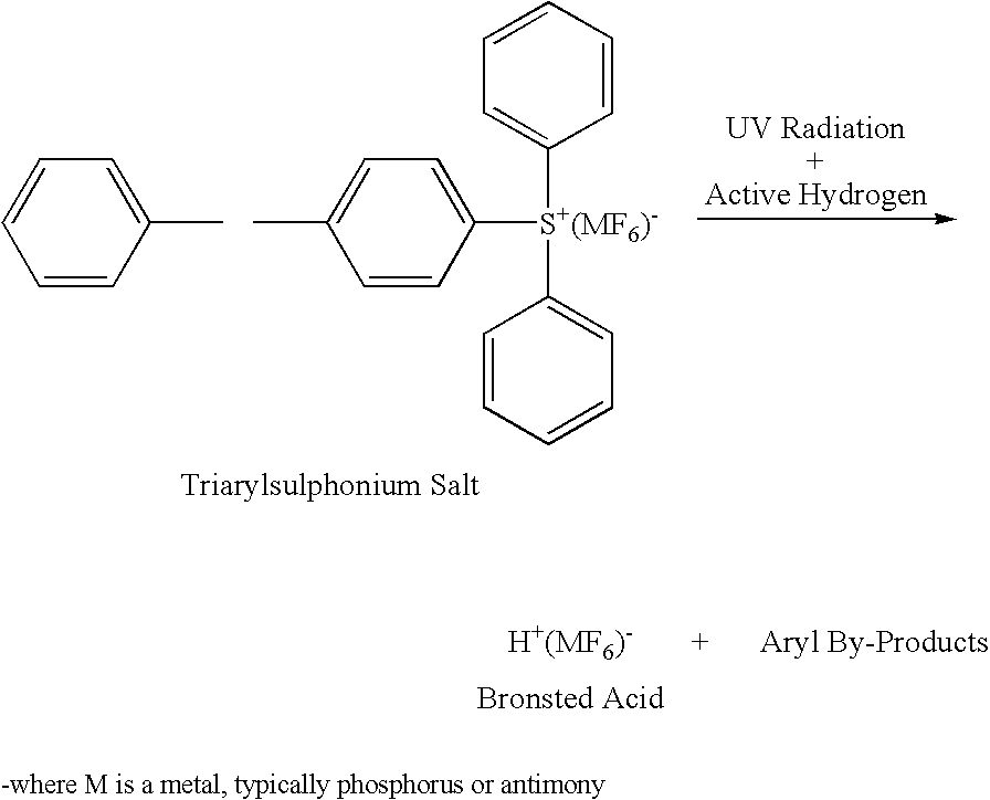
[0084]A functional ethylene terpolymer (E-MA-GMA) containing 24% by weight methyl acrylate and 8% by weight glycidyl methacrylate and of density 0.94 g / cm3 and melt flow index 6 dg / min. was blended with an ethylene propylene diene terpolymer (EPDM) of density 0.908 g / cm3 and melt flow index 1.0 dg / min., a cationic photoinitiator comprising triarylsulphonium hexafluorophosphate in propylene carbonate, a free-radical photoinitiator comprising 1-hydroxy-cyclohexylphenylketone and benzophenone, and a trimethylolpropane triacrylate crosslinking promoter, in the amounts shown in Table 1. The liquid cationic photoinitiator, free-radical photoinitiator and crosslinking promoter were imbibed into a porous HDPE carrier at a ratio of approximately 2:1 to aid blending with the polymeric components. Blending was accomplished with a tumble blender, ribbon blender, high-speed blender, or multi-component feeding system.

[0085]The blended components were fed through a 24:1 L / D single-screw extruder, ...

example 1b

[0088]The molten extruded sheet of Example 1a was wrapped circumferentially around the surface of a rotating steel pipe previously coated with an epoxy-based corrosion protection layer, and UV crosslinked using a series of UV lamps positioned circumferentially around the pipe.

example 1c

[0089]The composition of Example 1a was extruded through an annular die, the tube or pipe thus formed being cooled and UV crosslinked as described above. The crosslinked tube or pipe may subsequently be rendered heat-shrinkable by re-heating, stretching, and cooling as described above.


PUM

PropertyMeasurementUnit
wavelengthaaaaaaaaaa
temperaturesaaaaaaaaaa
thicknessaaaaaaaaaa

Abstract

A photo-crosslinkable polyolefin composition comprises a polyolefin, a source of functionality receptive to crosslinking by UV radiation, a cationic photoinitiator and optionally includes a free-radical photoinitiator, a crosslinking accelerator or sensitizer, and other additives such as compatibilizers, inorganic fillers, nanofillers, glass, polymeric and ceramic microspheres, glass fibres, flame retardants, antioxidants, stabilizers, processing aids, foaming agents and pigments. A method for manufacturing a UV-crosslinked polyolefin article comprises forming an article by extruding, moulding or otherwise forming the UV-crosslinkable polyolefin composition and subjecting the article to UV radiation on-line with the extrusion, moulding or other forming operation.

Description

FIELD OF THE INVENTION[0001]The present invention relates to polymer compositions, articles made therefrom, and methods for the production and processing of these compositions and articles. More particularly, the compositions according to the invention are polyolefin-based compositions and are crosslinkable by exposure to ultraviolet radiation. The articles according to the invention are coatings and insulating materials. The invention allows on-line crosslinking of the polymer during production of the articles.BACKGROUND OF THE INVENTION[0002]Due to an attractive balance of performance and cost, polyolefin resins, such as polyethylenes, polypropylenes, copolymers of ethylene and propylene, and compositions based thereon, are widely used in coating and insulation applications. These applications include: heat-shrinkable corrosion-protection sleeves for oil and gas pipeline joints; solid and foamed coatings for the corrosion, mechanical and thermal protection of pipelines and pipelin...

Claims


Application Information

Patent Timeline
Patent Type & Authority Applications(United States)
IPC IPC(8): C08F2/50C08J3/28
CPCC08J3/243C08J2323/00C09D151/06C08L2314/06C08L2312/06C08L2205/02C08K7/14C08L21/00C08L23/04C08L23/06C08L23/0884C08L23/10C08L23/16C08L51/06C08L2666/06C08L2666/08C08L2666/24C08L2666/04C08L2666/02Y10T428/31909Y10T428/31938
Inventor JACKSON, PETERWAN, EILEEN
Owner SHAWCOR LTD
Why Eureka
Try Eureka