Eureka AIR delivers breakthrough ideas for toughest innovation challenges, trusted by R&D personnel around the world.

Light emitting polymer composition and polymer light emitting device

a technology of light-emitting devices and polymer compositions, applied in the direction of discharge tube luminescnet screens, organic semiconductor devices, organic chemistry, etc., can solve the problems of unsatisfactory device efficiency, and achieve the effect of high efficiency

Inactive Publication Date: 2009-02-12
SUMITOMO CHEM CO LTD
View PDF8 Cites 23 Cited by
  • Summary
  • Abstract
  • Description
  • Claims
  • Application Information

AI Technical Summary

Benefits of technology

[0004]The present invention has an object of providing a light emitting polymer composition which can impart a light emitting device of high efficiency when used in a light emitting layer of the light emitting device.
[0096]Of charge transport layers provided adjacent to an electrode, those having a function of improving efficiency of charge injection from an electrode and having an effect of lowering the driving voltage of a device are sometimes referred to particularly as charge injection layer (hole injection layer, electron injection layer) in general.
[0119]The insulation layer having a thickness of 2 nm or less has a function of facilitating charge injection. As the material of the insulation layer, metal fluorides, metal oxides, organic insulation materials and the like are mentioned. As the polymer LED having an insulation layer having a thickness of 2 nm or less, there are a polymer LED having an insulation layer having a thickness of 2 nm or less provided adjacent to a cathode, and a polymer LED having an insulation layer having a thickness of 2 nm or less provided adjacent to an anode.
[0151]In the polymer LED composition of the present invention, further higher efficiency can be obtained by combining with a hole transport layer made of a polyamine having a repeating unit derived particularly from an aromatic amine. As the polyamine, those containing repeating unit of the formula (3) are preferable, and further preferably, those containing repeating unit of the formula (4) are advantageous.
[0167]As the protective layer, polymer compounds, metal oxides, metal fluorides, metal borides and the like can be used. As the protective cover, glass plates, plastic plates on which a water permeability lowering treatment has been performed, and the like can be used, and a method is suitably used in which the cover is sealed by pasting with a device base plate with a thermosetting resin or photo-curing resin. When a space is maintained using a spacer, injuring of a device can be easily prevented. If an inert gas such as nitrogen or argon is filled in the space, oxidation of a cathode can be prevented, and further by placing a desiccant such as barium oxide and the like in the space, a damage on a device by moisture adsorbed in a production process can be easily suppressed. Of them, one or more strategies are preferably adopted.

Problems solved by technology

However, when light emitting polymers are used, the device efficiency thereof is not satisfactory yet.

Method used


Image

  • Light emitting polymer composition and polymer light emitting device
  • Light emitting polymer composition and polymer light emitting device
  • Light emitting polymer composition and polymer light emitting device

Examples


synthesis example 1

Synthesis of 4-t-butyl-2,6-dimethylbromobenzene

[0176]

[0177]Under an inert atmosphere, into a 500 ml three-necked flask was placed 225 g of acetic acid, and 24.3 g of 5-t-butyl-m-xylene was added. Subsequently, 31.2 g of bromine was added, then, reacted at 15 to 20° C. for 3 hours.

[0178]The reaction liquid was added to 500 ml of water and the deposited precipitate was filtrated. The precipitate was washed with 250 ml of water twice, to obtain 34.2 g of white solid.

[0179]1H-NMR (300 MHz / CDCl3):

[0180]δ(ppm) 1.3 [s, 9H], 2.4 [s, 6H], 7.1 [s, 2H]

[0181]MS (FD+) M+ 241

synthesis example 2

Synthesis of N,N′-diphenyl-N,N′-bis(4-t-butyl-2,6-dimethylphenyl)-1,4-phenylenediamine

[0182]

[0183]Under an inert atmosphere, into a 100 ml three-necked flask was placed 36 ml of deaerated dehydrated toluene, and 0.63 g of tri(t-butyl)phosphine was added. Subsequently, 0.41 g of tris(dibenzylideneacetone)dipalladium, 9.6 g of the above-described 4-t-butyl-2,6-dimethylbromobenzene, 5.2 g of t-butoxysodium and 4.7 g of N,N′-diphenyl-1,4-phenylenediamine were added, then, reacted at 100° C. for 3 hours.

[0184]The reaction liquid was added to 300 ml of saturated saline and extracted with 300 ml of chloroform warmed at about 5° C. The solvent was distilled off, then, 100 ml of toluene was added and the mixture was heated until dissolution of solid and allowed to cool, then, the precipitate was filtrated to obtain 9.9 g of white solid.

synthesis example 3

Synthesis of N,N′-bis(4-bromophenyl)-N,N′-bis(4-t-butyl-2,6-dimethylphenyl)-1,4-phenylenediamine

[0185]

[0186]Under an inert atmosphere, into a 1000 ml three-necked flask was placed 350 ml of dehydrated N,N-dimethylformamide, and 5.2 g of the above-described N,N′-diphenyl-N,N′-bis(4-t-butyl-2,6-dimethylphenyl)-1,4-phenylenediamine was dissolved, then, N-bromosuccinimide 3.5 g / N,N-dimethylformamide solution was dropped in an ace bath, and reacted over night and day.

[0187]150 ml of water was added to the reaction liquid, and the deposited precipitate was filtrated and washed with 50 ml of methanol twice to obtain 4.4 g of white solid.

[0188]1H-NMR (300 MHz / THF-d8):

[0189]δ(ppm)=1.3 [s, 18H], 2.0 [s, 12H], 6.6˜6.7 [d, 4H], 6.8˜6.9 [br, 4H], 7.1 [s, 4H], 7.2˜7.3 [d, 4H]

[0190]MS (FD+) M+ 738


PUM

PropertyMeasurementUnit
Timeaaaaaaaaaa
Percent by massaaaaaaaaaa

Abstract

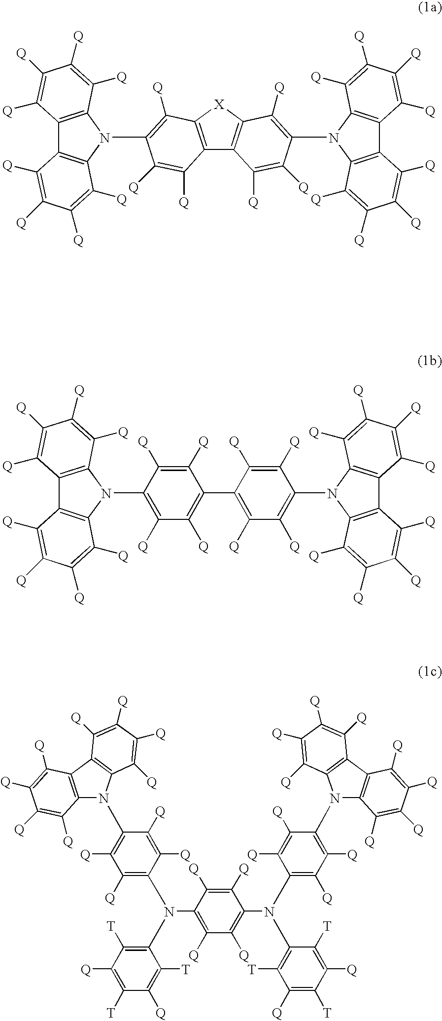
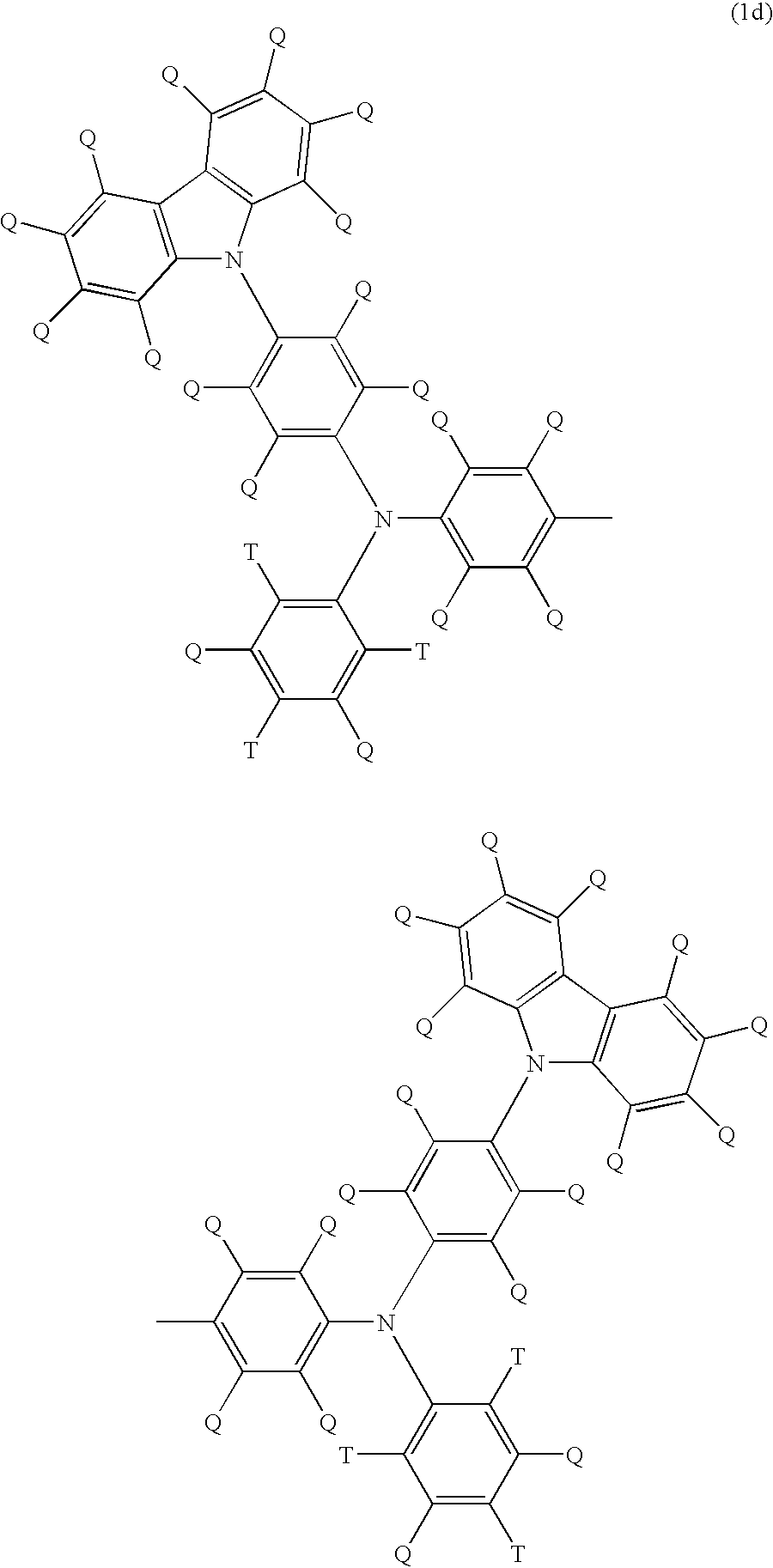
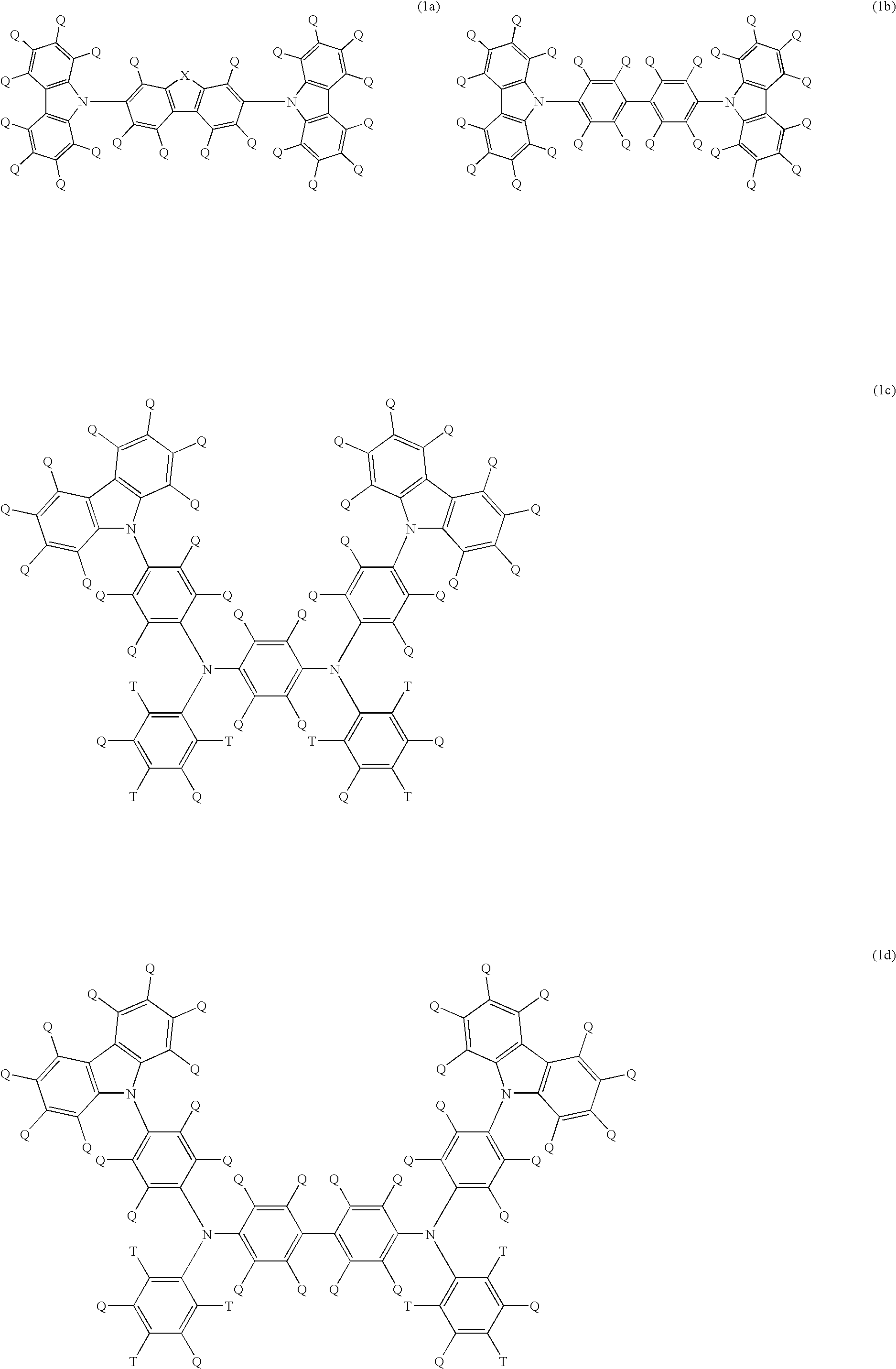
A light emitting polymer composition comprising a light emitting polymer and a compound selected from the following formulae (1a) to (1d):(wherein, X represents an atom or atomic group forming a 5-membered or 6-membered ring together with four carbon atoms on two benzene rings in the formula, Q and T represent each independently a hydrogen atom, halogen atom, alkyl group, alkyloxy group, alkylthio group, aryl group, aryloxy group, arylthio group, arylalkyl group, arylalkyloxy group, arylalkylthio group, alkenyl group, alkynyl group, arylalkenyl group, arylalkynyl group, substituted silyloxy group, substituted silylthio group, substituted silylamino group, substituted amino group, amide group, acid imide group, acyloxy group, mono-valent heterocyclic group, heteroaryloxy group, heteroarylthio group, cyano group or nitro group).

Description

TECHNOLOGICAL FIELD[0001]The present invention relates to a light emitting polymer composition, a light emitting polymer solution composition, and a polymer light emitting device (polymer LED) using the same.BACKGROUND ART[0002]Light emitting polymers (light emitting materials of high molecular weight) are soluble in a solvent, differing from those of low molecular weight, thus, capable of forming a light emitting layer in a light emitting device by an application method, responding to a requirement of larger area of the device. Therefore, there are recently suggested various polymer light emitting materials (for example, Advanced Materials Vol. 12, 1737-1750 (2000)).[0003]Here, light emitting devices are desired to show high light emitting efficiency, thus, high light emitting brilliance per electric current. However, when light emitting polymers are used, the device efficiency thereof is not satisfactory yet.DISCLOSURE OF THE INVENTION[0004]The present invention has an object of p...

Claims


Application Information

Patent Timeline
IPC IPC(8): H01J1/62C09K11/06C07D209/82
CPCC07D209/86H05B33/14C08K5/3417C08L65/00C09K11/06C09K2211/1425C09K2211/1433C09K2211/145C09K2211/1458C09K2211/1466C09K2211/1491C09K2211/182C09K2211/185H01L51/0035H01L51/0037H01L51/0052H01L51/0059H01L51/0061H01L51/0071H01L51/0072H01L51/0085H01L51/5012H01L2251/308C08K5/0091H10K85/111H10K85/1135H10K85/615H10K85/631H10K85/636H10K85/657H10K85/342H10K85/6572H10K50/11H10K2102/103C07D209/82C07D405/14C07D409/14C08L101/12
Inventor UETANI, YASUNORISHIRASAWA, NOBUHIKONAKANISHI, HIROTOSHI
Owner SUMITOMO CHEM CO LTD
Why Eureka
Eureka Blog
Learn More