Device for protecting metallic surfaces from high-temperature condensates of corrosive media in technical installations

a technology of corrosive media and protective devices, which is applied in the field of protective devices for metallic surfaces from high-temperature condensates of corrosive media in technical installations, can solve the problems of acid corrosion on the interior walls of steel sheet cladding, damage to steel sheet cladding, and the formation of polluted condensates of liquid water, so as to increase the thermal insulation effect, increase the temperature resistance of gas-vapor mixture barriers, and reduce the effect of energy consumption

Inactive Publication Date: 2009-02-12
TH JANSEN ARMATUREN
View PDF9 Cites 7 Cited by
  • Summary
  • Abstract
  • Description
  • Claims
  • Application Information

AI Technical Summary

Benefits of technology

[0047]The advantage of the present invention is that when using a gas-vapor barrier the thermal insulation effect is increased and the consumption of energy falls since the steel sheet cladding temperature can be lowered to correspond with or be lower than the ambient air temperature as it no longer is relevant if the temperature falls below the dew point temperature on the interior.
[0051](c) integrating it within the thermal insulation in a multi-layered structure.
[0052]The advantage of variant (a) is that when the gas-vapor mixture barrier is fitted between the refractory lining and the thermal insulation it can be done in such a way that no water reaches the thermal insulation which means that it does not necessarily have to be made from water repellent materials. Water repellent materials are used in the manufacturing of thermal insulation due to the processing of the refractory lining. Water is used when processing refractory concrete or lightweight refractory concrete and this water reaches the material used for the thermal insulation.
[0053]The higher the temperature resistance of the gas-vapor mixture barrier is the closer it can...

Problems solved by technology

Acid corrosion on the interior walls of the steel sheet cladding is caused by corrosive liquid that forms from condensation of humid air and that contains gaseous pollutants from the areas of the blast furnace stove, the hot blast pipes and the hot blast valves it has flowed through.
In addition to these chemical causes there are also thermal influences related to high temperatures and temperature fluctuations which cause or accelerate corrosion.
If the temperature of the steel sheet cladding is lower than the dew point temperature, polluted condensates of liquid water will form.
The condensate which contains pollutants causes corrosion and thus damage to the steel sheet cladding.
If the temperature on the interior surface of the steel sheet cladding is maintained at a level significantly above the dew point temperature, temperature related humidity and tensile strain problems arise.
The expansion and shrinking movements caused by tensile strains which inherently occur during the heating and blast phases of the hot blast process result in alternating strain with a load change frequency ranging from between 5000 and 8000 per year and damage caused to the most brittle protecting layers of the cladding sheets and to the blast furnace stove, hot blast pipe and hot blast valve.
However, during the hot blast phase the damaging gases are blown into the hot blast pipe, the hot blast valve and the blast furnace pipe where condensation could then form.
In addition to the appearance of corrosion below the dew point temperature threshold, chemical reactions that cause corrosion also occur above the dew point threshold.
Ammonium nitrate NH4NO3, a saturated aqueous corrosion liquid, causes damage to the steel sheet cladding.
The presence of nitrogen oxides NOx during the various blast furnace stove phases cause the formation of the corrosion-causing ammonium nitrate.
have not had the desired results since nitrogen oxide transformation predominantly occurs while the blast furnace stove is being filled.
However, the gaseous atmosphere of the blast furnace...

Method used


Image

  • Device for protecting metallic surfaces from high-temperature condensates of corrosive media in technical installations
  • Device for protecting metallic surfaces from high-temperature condensates of corrosive media in technical installations
  • Device for protecting metallic surfaces from high-temperature condensates of corrosive media in technical installations

Examples


Embodiment Construction

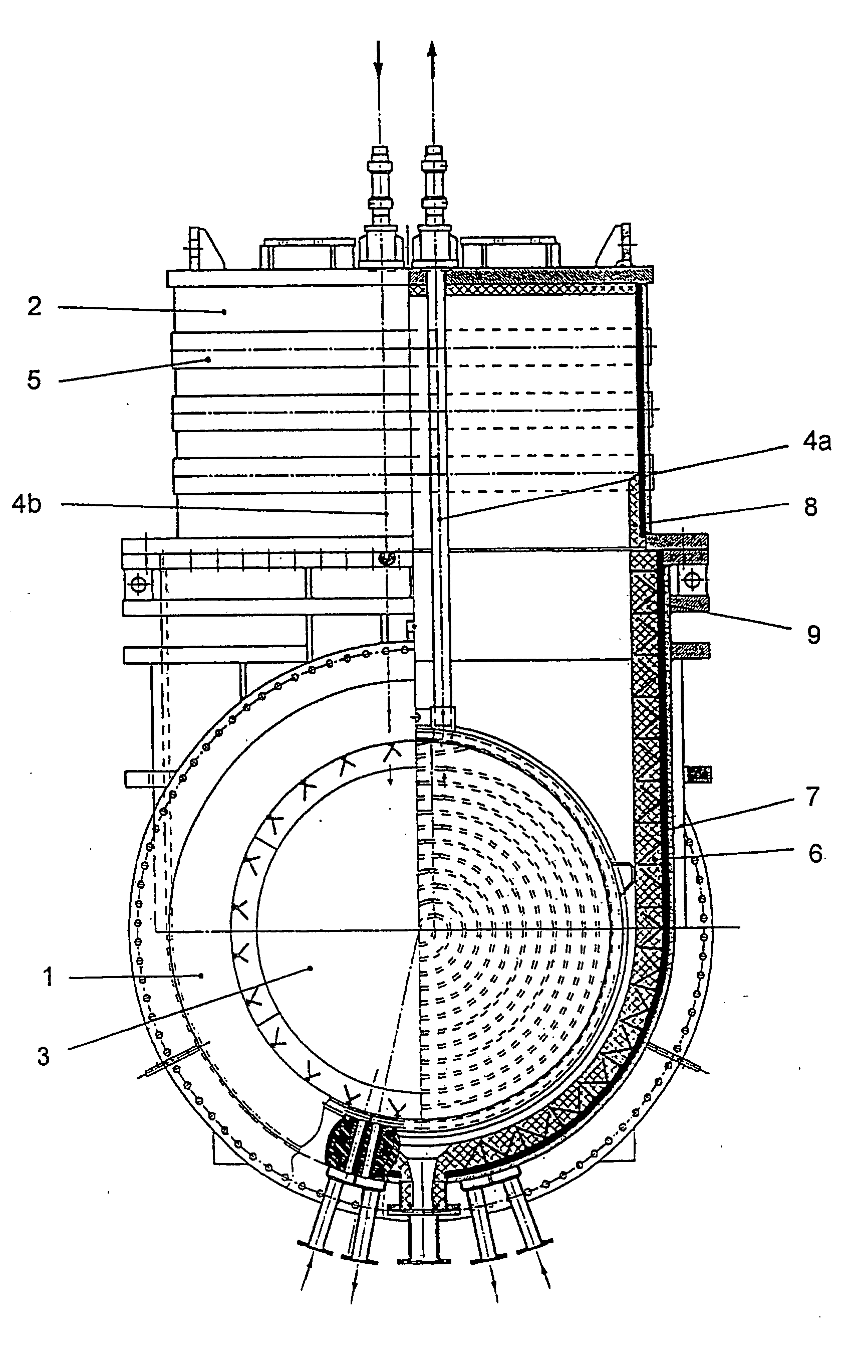
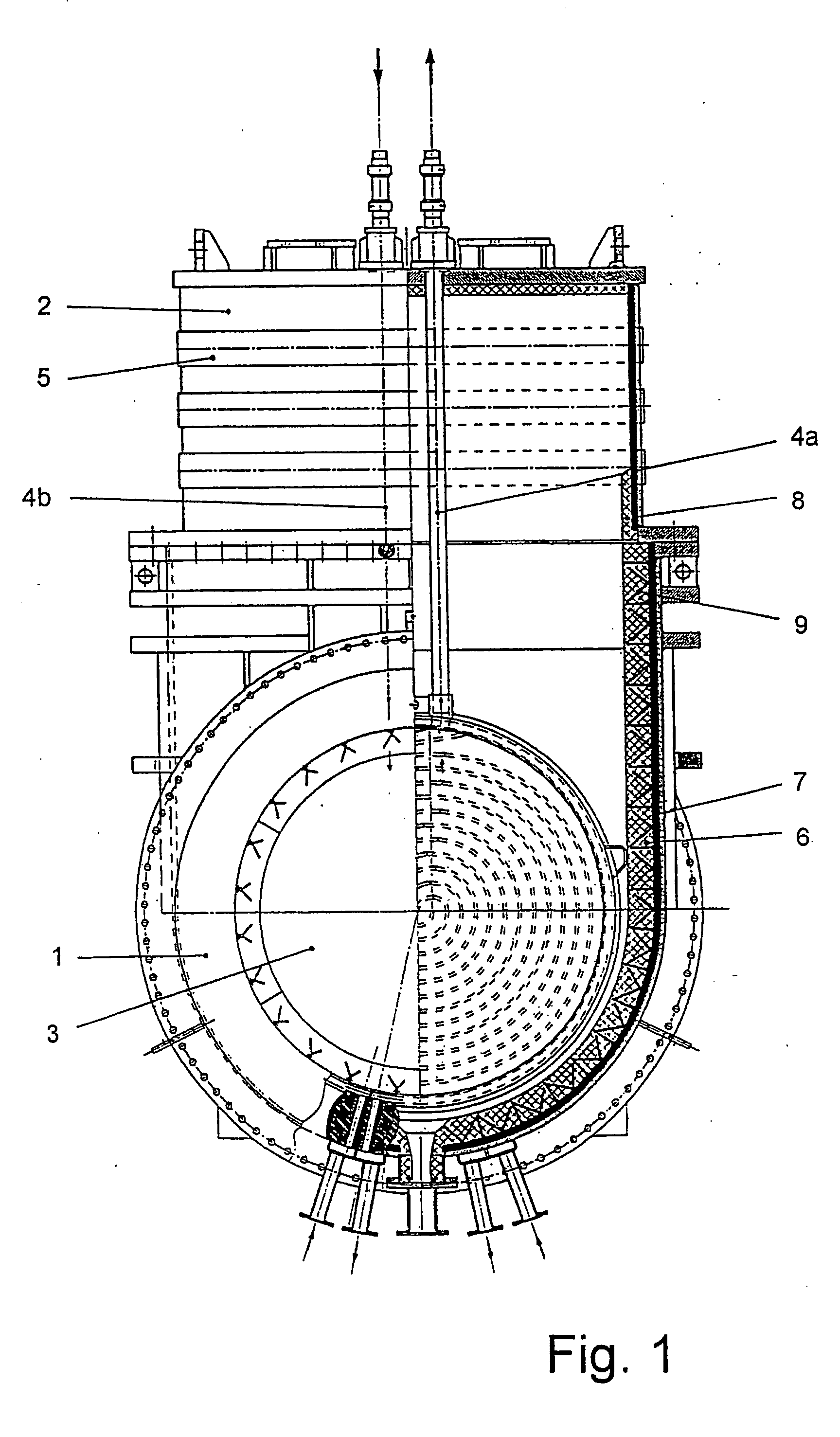
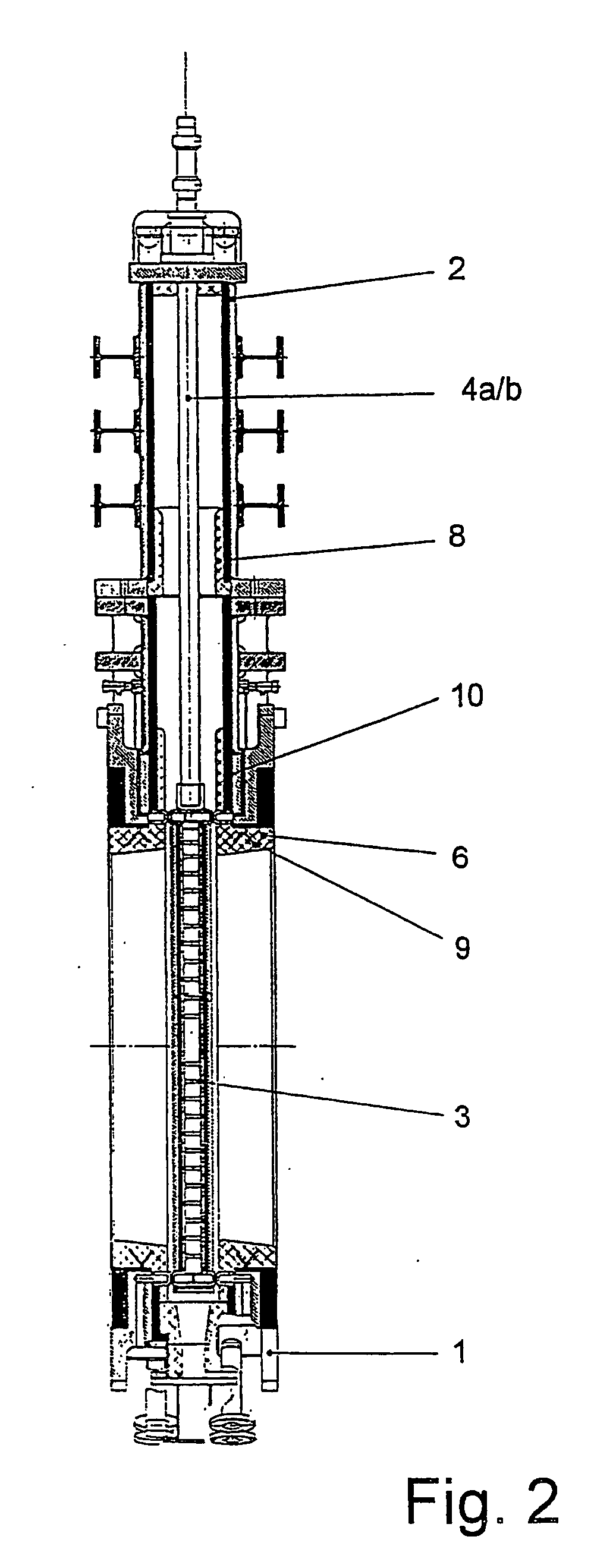
[0083]FIG. 1 shows a sectional view, perpendicular to flow direction, of a barrier device that is a hot blast valve. The valve housing 1 is fitted with a flange-mounted hood 2 into which can be slid a valve plate 3 that is shaped like a barrier device. This valve plate 3 is hollow and is fitted with spiral-shaped cooling agent channels through which a cooling agent runs. The valve plate 3 hangs on two connecting rods 4a, 4b which are hollow and at the same time function as inflow 4b and outflow 4a for the cooling agent. The connecting rods 4a and 4b run through a flange-mounted hood 2 which is fitted onto the upper side of the housing 1 and which is shaped in such a way that it can receive the valve plate 3 when the barrier device is in the open position. On the upper side of the hood 2 there are openings for the connecting rods 4a and 4b. Gland seals on the openings separate the interior space of the hot blast valve from the surroundings. Not shown here is the adjustment mechanism ...


PUM


Abstract

The supporting structure of a technical installation made from a material that is not resistant to corrosion and whose inner wall at least temporarily contains a corrosive and abrasive gas-vapor mixture and is protected from acid corrosion by a gas-vapor mixture barrier. This barrier is either placed between a refractory coating (6) and a thermal insulating layer (7) or is integrated into the refractory layer (6) or in the thermal insulating layer (7). The mechanical protection from the permeation of the gas-vapor mixture though the thermal insulation (7) up to the inner wall of the supporting structure allows a thermal insulating material to be selected that has a distinctly reduced thermal conductivity and thus allows the temperature on the exterior of the supporting structure to be lowered reducing energy consumption and improving occupational safety.

Description

BACKGROUND[0001]1. Field of the Invention[0002]The invention relates to technical installations such as blast furnace stoves comprising hot blast pipes and hot blast valves on which high-temperature condensates of gaseous corrosive media form which cause damage to the metallic walls of the technical installations. The invention particularly relates to a barrier device for high-temperature gaseous media used as a barrier for hot gas pipes that lead from a blast furnace stove to a blast furnace and which comprises a housing fitted with seal seats that are cooled by a cooling medium and a barrier element that is movable inside the housing and that is cooled by a cooling media whereby all surfaces that come into contact with the hot gas with the exception of the housing valve seals and the sealing surfaces on the barrier device are coated with a refractory coating.[0003]2. Background of the Invention[0004]DE 41 38 283 C1 discloses that all surfaces of a barrier device that are not coole...

Claims


Application Information

Patent Timeline
IPC IPC(8): F27D1/00
CPCF27D1/0006C21B9/06
Inventor MECKELNBURG, MICHAELGROSS, RENEWEBER, KURT
Owner TH JANSEN ARMATUREN
Why Eureka
Try Eureka