Dye-Sensitized Photoelectric Conversion Device

Inactive Publication Date: 2009-02-19
NIPPON KAYAKU CO LTD
View PDF31 Cites 23 Cited by
  • Summary
  • Abstract
  • Description
  • Claims
  • Application Information

AI Technical Summary

Benefits of technology

[0039]Using a methine dye having a specific structure, it became possible to provide a solar cell having high conversion efficiency and high stabili

Problems solved by technology

However, since a large amount of energy and high cost are required for production of such solar cells, they are problematic in terms of difficulty in generally using such solar cells.
However, in order to obtain a device with high conversion efficiency, a ruthenium complex is used as a sensitizing dye, and such

Method used


Image

  • Dye-Sensitized Photoelectric Conversion Device
  • Dye-Sensitized Photoelectric Conversion Device
  • Dye-Sensitized Photoelectric Conversion Device

Examples


synthesis example 1

[0090]56.8 parts of fluorene, 200 parts of methanol, 37 parts of 63% sulfuric acid aqueous solution, 31 parts of iodine, and 34 parts of 34% iodic acid aqueous solution were stirred at 60° C. for 5 hours. After completion of the stirring, the resultant was filtrated, and it was then washed with 100 parts of water twice. Thereafter, the resultant was dried at 70° C. overnight. After completion of the drying, the resultant was recrystallized in methanol to obtain 60 parts of 2-iodofluorene in the form of white powders.

synthesis example 2

[0091]20 parts of 2-iodofluorene was dissolved in a mixed solution of 114 parts of dimethyl sulfoxide (DMSO) and 23 parts of tetrahydrofuran (THF), and the thus obtained mixture was then stirred at 25° C. for 10 minutes. Thereafter, while stirring, 8.6 parts of potassium-tert-butoxide was added to the mixture. Twenty minutes later, 14.6 parts of butyl iodide was added to the mixture, and further twenty minutes later, 8.6 parts of potassium-tert-butoxide was added thereto. Further, twenty minutes later, 14.6 parts of butyl iodide was added thereto, and the obtained mixture was then stirred at 25° C. for 2 hours. After completion of the stirring, THF was distilled away from the reaction solution, and it was then extracted with toluene-water. The toluene phase was dried over magnesium sulfate, and toluene was then distilled away, thereby obtaining a brown tarry solid. This brown tarry solid was separated and purified by column chromatography (hexane-ethyl acetate) to obtain 25 parts of...

synthesis example 3

[0092]40 parts of 9,9-dibutyl-2-iodofluorene, 3.7 parts of aniline, 30 parts of potassium carbonate, 6 parts of copper powders (200 meshes), and 0.87 parts of 18-crown-6 were dissolved in 50 parts of dimethylformamide (DMF), and the obtained solution was reacted in a nitrogen atmosphere at 160° C. for 24 hours. After completion of the reaction, the reaction product was filtrated, and the filtrate was then extracted with ethyl acetate-water. The ethyl acetate phase was dried over magnesium sulfate, and the ethyl acetate was then distilled away, thereby obtaining a brown tarry substance. This brown tarry substance was separated and purified by column chromatography (hexane-ethyl acetate) to obtain 15 parts of 9,9-dibutyl-N-(9,9-dibutylfluorenyl)-N-phenylfluorenamine (the following Compound (344)) in the form of a colorless crystal.


PUM


Abstract

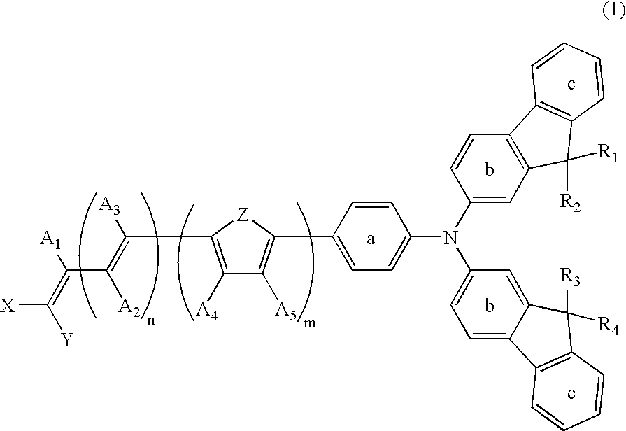
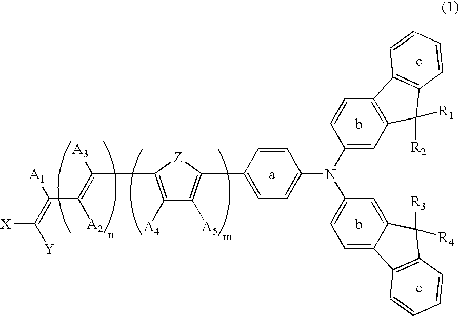
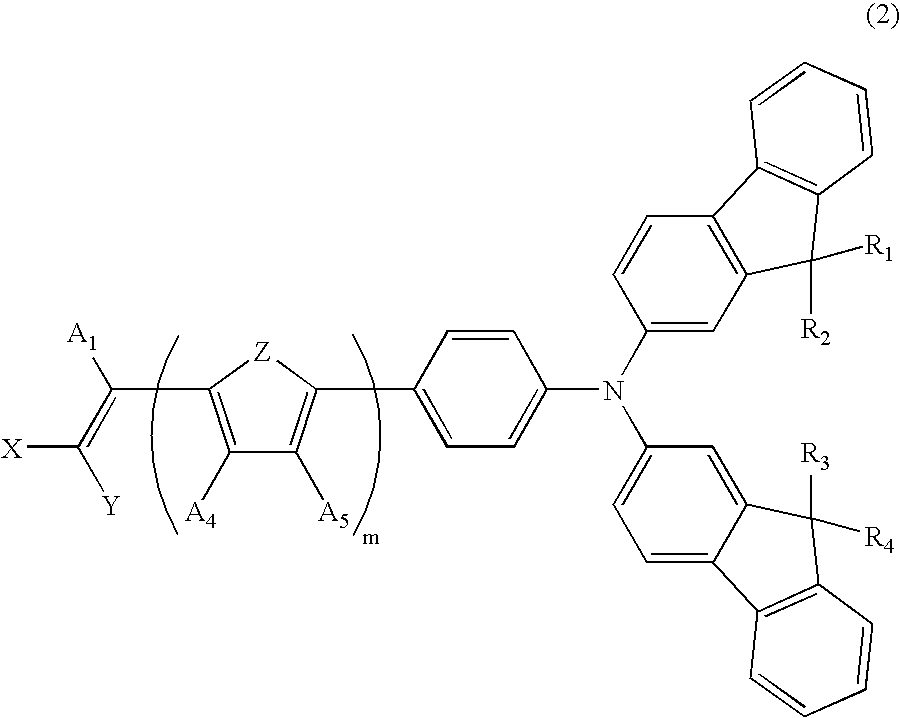
Disclosed is a photoelectric conversion device wherein a methine dye represented by the formula (1) below is supported by a thin film of oxide semiconductor particles arranged on a substrate. Also disclosed is a solar cell manufactured by using such a photoelectric conversion device.
(In the formula (1), n represents an integer of 0-5; m represents an integer of 0-5; R1-R4 independently represent a hydrogen atom, an optionally substituted aromatic residue, an optionally substituted aliphatic hydrocarbon residue or the like; X and Y independently represent a hydrogen atom; an optionally substituted aromatic residue, an optionally substituted aliphatic hydrocarbon residue or the like; Z represents an oxygen atom, a sulfur atom or the like; A1, A2, A3, A4 and A5 independently represent a hydrogen atom, an optionally substituted aromatic residue, an optionally substituted aliphatic hydrocarbon residue or the like; and rings a, b and c may be substituted.)

Description

TECHNICAL FIELD[0001]The present invention relates to a photoelectric conversion device having a thin film of oxide semiconductor fine particles that is sensitized with an organic dye, and a solar cell using the same. More specifically, the present invention relates to a photoelectric conversion device produced by supporting a methine compound (dye) with a specific structure on a thin film of oxide semiconductor fine particles, and a solar cell using the same.BACKGROUND ART[0002]A solar cell using sunlight has become a focus of attention as an energy resource alternative to fossil fuel such as petroleum or coal. At present, a silicon solar cell using crystalline or amorphous silicon, a compound semiconductor solar cell using gallium, arsenic, etc., and the like have vigorously been studied and developed. However, since a large amount of energy and high cost are required for production of such solar cells, they are problematic in terms of difficulty in generally using such solar cell...

Claims


Application Information

Patent Timeline
IPC IPC(8): H01L31/0216C07D409/14
CPCC09B23/0075C09B23/0091C09B23/14C09B23/143C09B23/145H01G9/2004Y02E10/549H01G9/2059H01L51/0053H01L51/006H01L51/0061H01L51/0068Y02E10/542H01G9/2031H10K85/621H10K85/636H10K85/633H10K85/655C09B23/00H01M14/00H01L31/04
Inventor SHIGAKI, KOICHIROKANEKO, MASAYOSHIHOSHI, TAKAYUKIINOUE, TERUHISA
Owner NIPPON KAYAKU CO LTD
Why Eureka
Try Eureka