Surface Coated Tool

a technology of surface coating and tool, which is applied in the field of surface coating tools, can solve the problems of shortening the life of the tool, affecting the quality of the tool, and insufficient wear resistance and fracture resistance as a whole hard coating layer, so as to achieve excellent wear resistance and fracture resistance, excellent cutting performance, and maintain the surface state of the tool. smooth

Inactive Publication Date: 2009-05-21
KYOCERA CORP
View PDF12 Cites 39 Cited by
  • Summary
  • Abstract
  • Description
  • Claims
  • Application Information

AI Technical Summary

Benefits of technology

[0022]The main advantage of the present invention is to provide a surface coated tool with a hard coating layer which has fine and homogeneous structure irrespective of condition such as unevenness of a substrate surface and the like, and has excellent wear resist

Problems solved by technology

In contrast, unevenness on the surface of the substrate and variations of a nucleation status at the initial phase of layer formation cause heterogeneous structure and composition in the hard coating layer, so that wear resistance and fracture resistance as a whole hard coating layer are not necessarily sufficient.
Particularly, a cutting tool having a sharp cutting edge and used for precision work that required smoothness of a finished surface has the following problems.
That is, minute layer peeling and chipping occur on the cutting edge at the initial phase of work, finished surface roughness deteriorates, thereby the tool life becomes shorter.
In contrast, there are problems that hardness of the hard coating layer decreases and wear resistance deteriorates.
Further, because of introduction of many lattice defects, TiAlN layer growth is heterogeneous, homogeneity of the hard coating layer is impaired, and finished surface roughness is liable to deteriorate.
However, the layer having a grain diameter of 50 nm or less in the TiAlN layer, as described in Patent Document No. 3, improves wear resistance, whereas internal stress excessively accumulates therein.
Therefore, fracture resistance is deteriorated due to a deficiency of a str

Method used


Image

  • Surface Coated Tool
  • Surface Coated Tool
  • Surface Coated Tool

Examples


example i

Manufacturing of Cutting Tools

[0089]A mixture was obtained by mixing tungsten carbide (WC) powder that is a main component and has a mean grain diameter of 0.8 μm, 10% by mass of metal cobalt (Co) powder having a mean grain diameter of 1.2 μm, 0.2% by mass of vanadium carbide (VC) powder having a mean grain diameter of 1.0 μm, and 0.6% by mass of chromium carbide (Cr3C2) powder having a mean grain size of 1.0 μm. Then, above mixture was press-formed into a shape of cutting tool for grooving (GBA43R300MY, grooving chip, manufactured by KYOCERA Corporation) having triangle shape. This was then subjected to debinding process, followed by sintering in vacuum of 0.01 Pa at 1450° C. for one hour, thereby manufacturing cemented carbide. The surface of rake face of each sample was polished by blasting or brushing. The cemented carbide was further subjected to cutting edge treatment (honing) by brushing, so that the substrate was obtained.

[0090]A hard coating layer was formed on the substrat...

example ii

Manufacturing of Cutting Tools

[0103]A mixture was obtained by mixing tungsten carbide (WC) powder that is a main component and has a mean grain diameter of 0.8 μm, 10% by mass of metal cobalt (Co) powder having a mean grain diameter of 1.2 μm, 0.2% by mass of vanadium carbide (VC) powder having a mean grain diameter of 1.0 μm, and 0.6% by mass of chromium carbide (Cr3C2) powder having a mean grain size of 1.0 μm. Then, above mixture was press-formed into a shape of cutting tool for indexable milling (BDMT11T308ER-JT). This was then subjected to debinding process, followed by sintering in vacuum of 0.01 Pa at 1450° C. for one hour, thereby manufacturing cemented carbide. The surface of rake face of each sample was polished by blasting or brushing. The cemented carbide was further subjected to cutting edge treatment (honing) by brushing, so that the substrate was obtained.

[0104]A hard coating layer was formed on the substrate in various kinds of composition as shown in Table 3 by sput...

example iii

Manufacturing of Cutting Tools

[0116]A mixture was obtained by preparing cBN raw material powder having a mean grain diameter of 2.5 μm, TiC raw material powder having a mean grain diameter of 1.5 μm, TiN raw material powder having a mean grain diameter of 1.2 μm, TiCN raw material powder having a mean grain diameter of 1 μm, NbC raw material powder having a mean grain diameter of 1 μm, TaC raw material powder having a mean grain diameter of 1.1 μm, Ni raw material powder having a mean grain diameter of 0.9 μm, metal Al raw material powder having a mean grain diameter of 1.2 μm, and metal Co raw material powder having a mean grain diameter of 0.8 μm in order to be the composition shown in Table 5, and mixing for 16 hours in a ball mill using the ball made from alumina. Above mixture was then subjected to pressing under the pressure of 98 MPa. The green body thus obtained was subjected to heating at a pace shown in Table 5, with ultra-high pressure and temperature apparatus, followed ...


PUM

PropertyMeasurementUnit
Lengthaaaaaaaaaa
Lengthaaaaaaaaaa
Lengthaaaaaaaaaa

Abstract

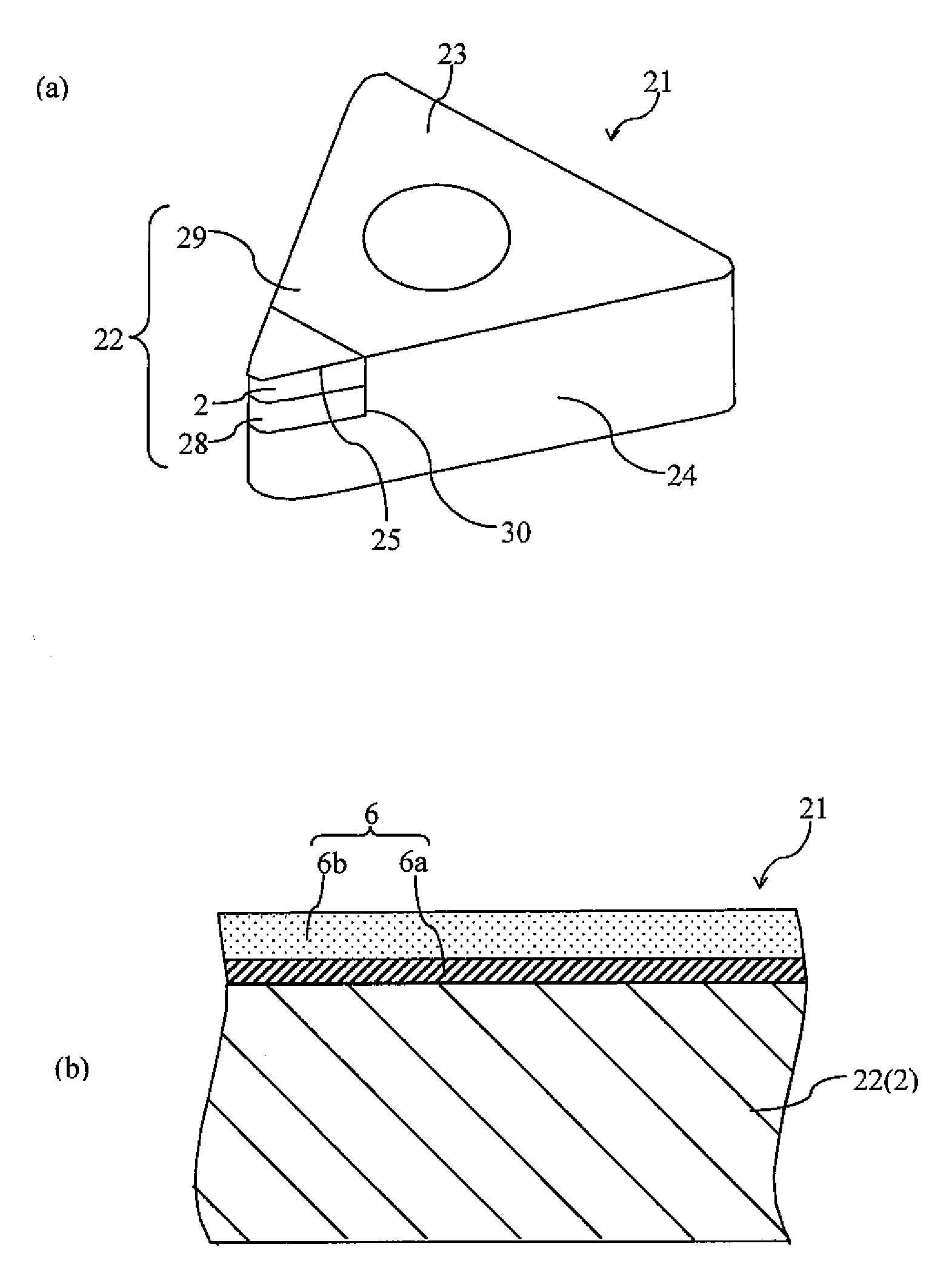
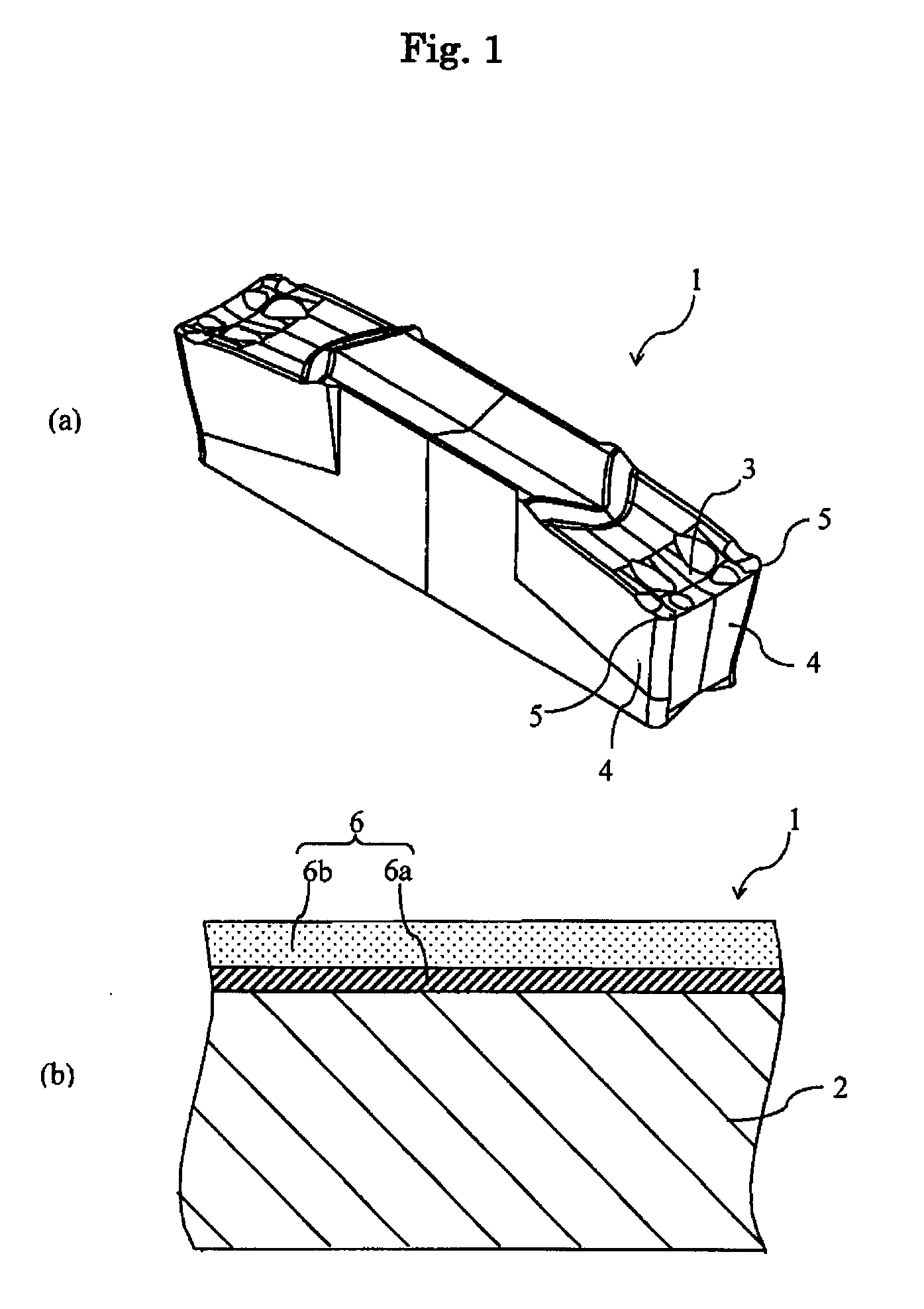
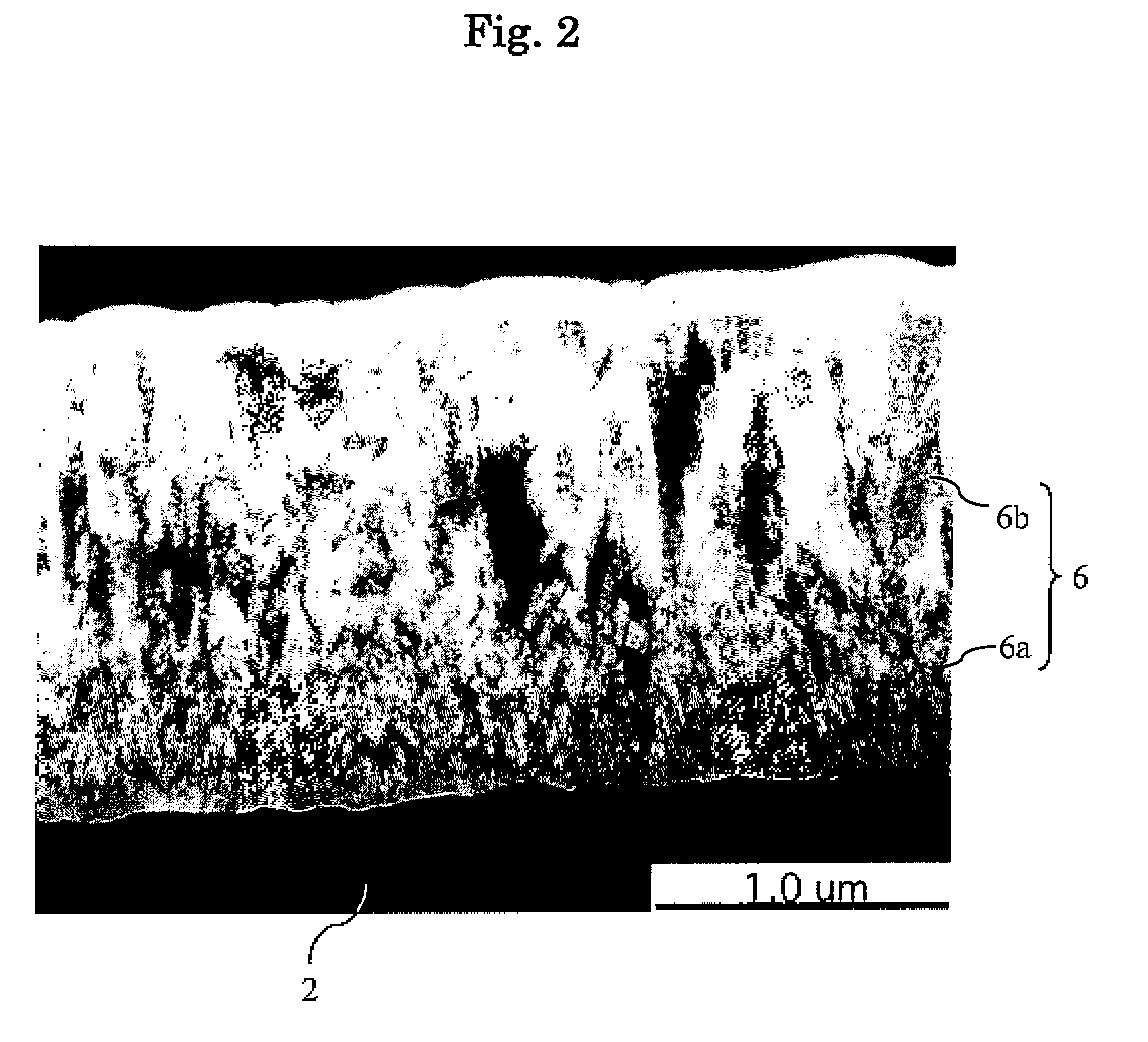
A surface coated tool including a substrate, and stacked layers composed of two coating layers represented by the following general formula (1) on the substrate is provided. A first coating layer to be coated on the surface of the substrate, which has a thickness of 0.1 to 1 μm, is composed of a granular crystal having a mean crystal diameter of 0.01 to 0.1 μm. A second coating layer to be coated on the surface of the first coating layer, which has a thickness of 0.5 to 5 μm, is composed of columnar crystal grown in a direction perpendicular to the substrate, and the columnar crystal has a mean crystal width of 0.05 to 0.3 μm in a direction parallel to the substrate while a mean crystal width thereof is larger than the mean crystal diameter of the first coating layer.
    • [Formula 3]
M1-aAla(CbN1-b)  (1)
    • wherein, M represents at least one metal element selected from the group consisting of the elements of Groups 4, 5 and 6 of the periodic table, Si and rare earth elements, “a” satisfies the relation of 0.25≦a≦0.75, and “b” satisfies the relation of 0≦b≦1.

Description

TECHNICAL FIELD[0001]The present invention relates to a surface coated tool forming a hard coating layer on a surface of a substrate.BACKGROUND ART[0002]Recently, the surface coated tool is obtained by forming various hard coating layers on a surface of a hard material such as WC-based cemented carbide and TiCN-based cermet so as to improve sliding performance, wear resistance and fracture resistance. Particularly a hard coating layer formed by physical vapor deposition method, which has high hardness and high wear resistance, is widely used for various purposes. A TiAlN layer is formed by are ion plating method and sputtering method as the physical vapor deposition method, and is considered improvement for extending the life of the cutting tool.[0003]For example, Patent Document No. 1 describes that a hard layer is configured by alternately stacking the TiAlN layer having low hardness and the TiAlN layer having high hardness, so that adhesion to the substrate of the hard layer and ...

Claims


Application Information

Patent Timeline
IPC IPC(8): B32B5/16B23B27/14
CPCB23B2224/04Y10T428/256B23B2224/36B23B2228/105C04B35/58014C04B35/58021C04B35/581C04B2235/3852C04B2235/3856C04B2235/3865C04B2235/3873C04B2235/3886C23C14/0036C23C14/0664Y10T407/27B23B2224/24
Inventor ZHU, YAOCANNODA, KENJIMATSUZAWA, MASAHITO
Owner KYOCERA CORP
Why Eureka
Try Eureka