Methane separation method, methane separation apparatus, and methane utilization system

Inactive Publication Date: 2009-06-18
TAIYO NIPPON SANSO CORP +1
View PDF2 Cites 36 Cited by
  • Summary
  • Abstract
  • Description
  • Claims
  • Application Information

AI Technical Summary

Benefits of technology

[0044]According to the first embodiment of the present invention, the mixed fluid in a gas-liquid mixed phase formed in the mixer is introduced into the first gas/liquid separator and the separated methane is recovered. Thereafter, the CO2-absorbed liquid is supplied to the inside of the membrane module, and the pressure outside the permeable membrane is lowered to a level lower than that inside the permeable membrane. Since the separation of carbon dioxide accelerates due to this configuration, methane can be separated and purified at high efficiency from the biogas containing high concentration of carbon dioxide. Therefore, the present invention is capable of reducing power load and membrane module cost and can carry out the separation/concentration of biogases at a low separation cost compared to the already available apparatuses that employ the PSA process, the dry membrane separation process, the chemical absorption method, or the like by adopting the membrane/absorption hybrid method. Since most methane contained in the biogas can be recovered merely by the first gas/liquid separator, simplification of the apparatus configuration and price reduction of the methane separation apparatus will be possible. In addition, power load can be reduced by lowering the flow rate of excessive CO2-absorbed liquid pouring out from the exhaust port of the membrane module down to a minimum level.
[0045]Various mixers capable of dispersing the biogas as minute bubbles in the absorbing liquid can be used as the aforementioned mixer. Specifically, stand alone mixers such as an ejector, a mixer, an aerator, and a packed bubble column of a gas-liquid co-current which is a gas-liquid contacting column where a filler is filled, or combined mixers that combine two or more of the above mixers can be used.
[0046]According to the second embodiment of the present invention, further improvements in the methane separation can be achieved since an excessive CO2-absorbed liquid discharged from the exhaust port of the membrane module is introduced to the second gas/liquid separator and the reseparation/recovering of the remaining trace amount of methane is carried out.
[0047]The third and fourth embodiments of the present invention contribute to the improvements in methane separation performance. It has become apparent due to the verification of the present inventors that at the time of carbon dioxide release in the regeneration step of the absorbing liquid, congestion of the membrane module prevents the release. In other words, the packing density of permeable membranes affects the performance of carbon dioxide release in the membrane module. The packing density of hollow fiber permea

Problems solved by technology

In the low temperature processing method, the separation process involves the comings and goings of heat and it is not preferable from an economical viewpoint since an apparatus will be complex and also will be large in size if highly pure methane were to be obtained efficiently.
Accordingly, there has been a problem of increase in the initial cost as well as the operation cost for gas separation due to the absorption column for efficiently bringing the absorbing liquid into contact with the target gas and a large amount of heating energy required for the release.
Moreover, the requirement for a large amount of water for purifying bio gases has also been a problem, although there is a so-called carbonate absorption process available which exploits the effect that carbon dioxide dissolves in water and uses high pressure water.
However, since the differences in the permeation rates among the membranes are exploited in the dry membrane separation process, it is necessary to increase the number of steps in the membrane module in order to obtain highly pure methane resulting in higher cost, which has been a problem.
However, in the PSA process, a pressure range in which an apparatus is operated needs to be set within a wide range of −90 KPaG to 0.7 MPaG in order to obtain highly pure methane, and thus the resulting high power cost is a problem.
In addition, recovery rate needs to be sacrificed in order to obtain highly pure methane which leads to the generation of a

Method used


Image

  • Methane separation method, methane separation apparatus, and methane utilization system
  • Methane separation method, methane separation apparatus, and methane utilization system
  • Methane separation method, methane separation apparatus, and methane utilization system

Examples


example 1

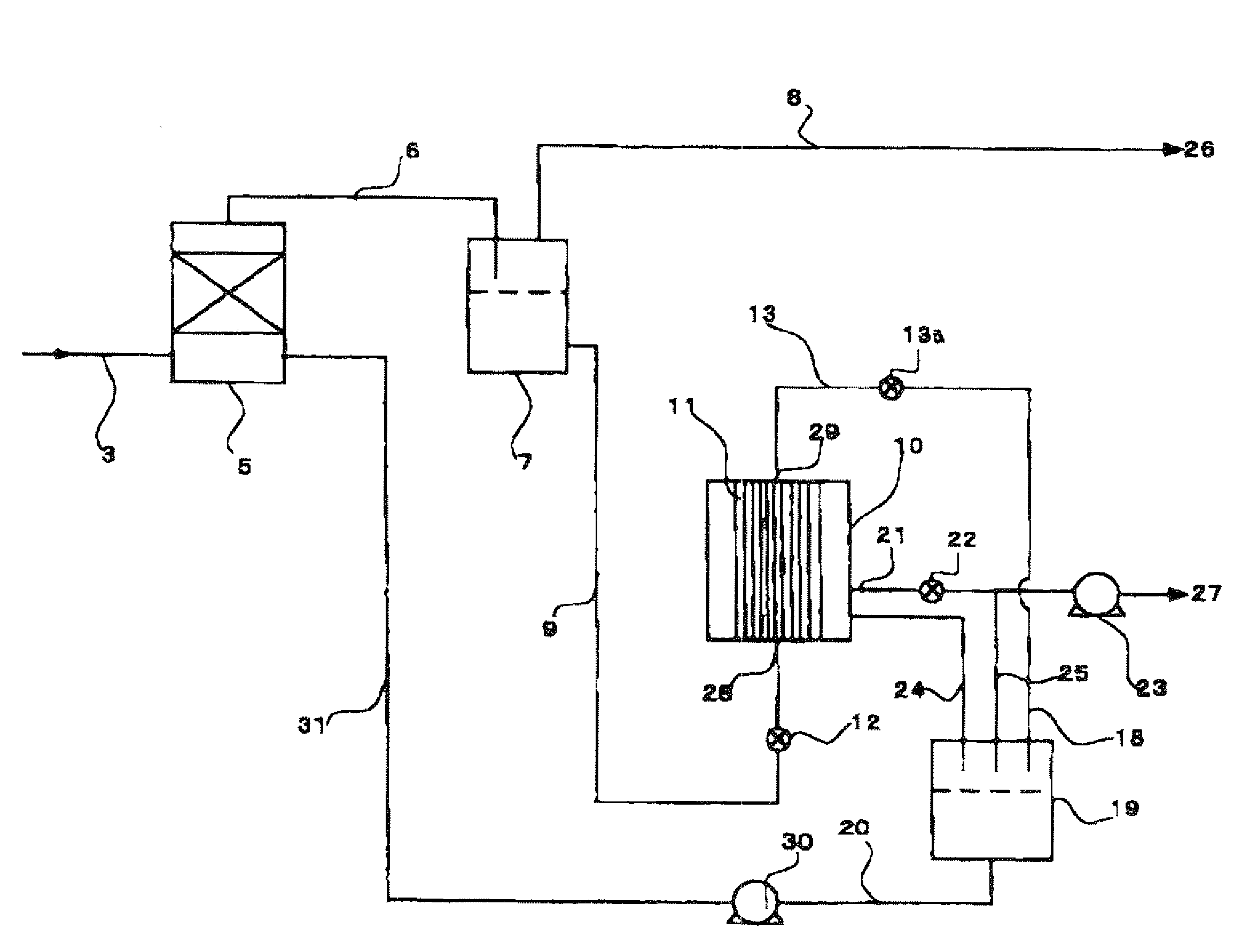
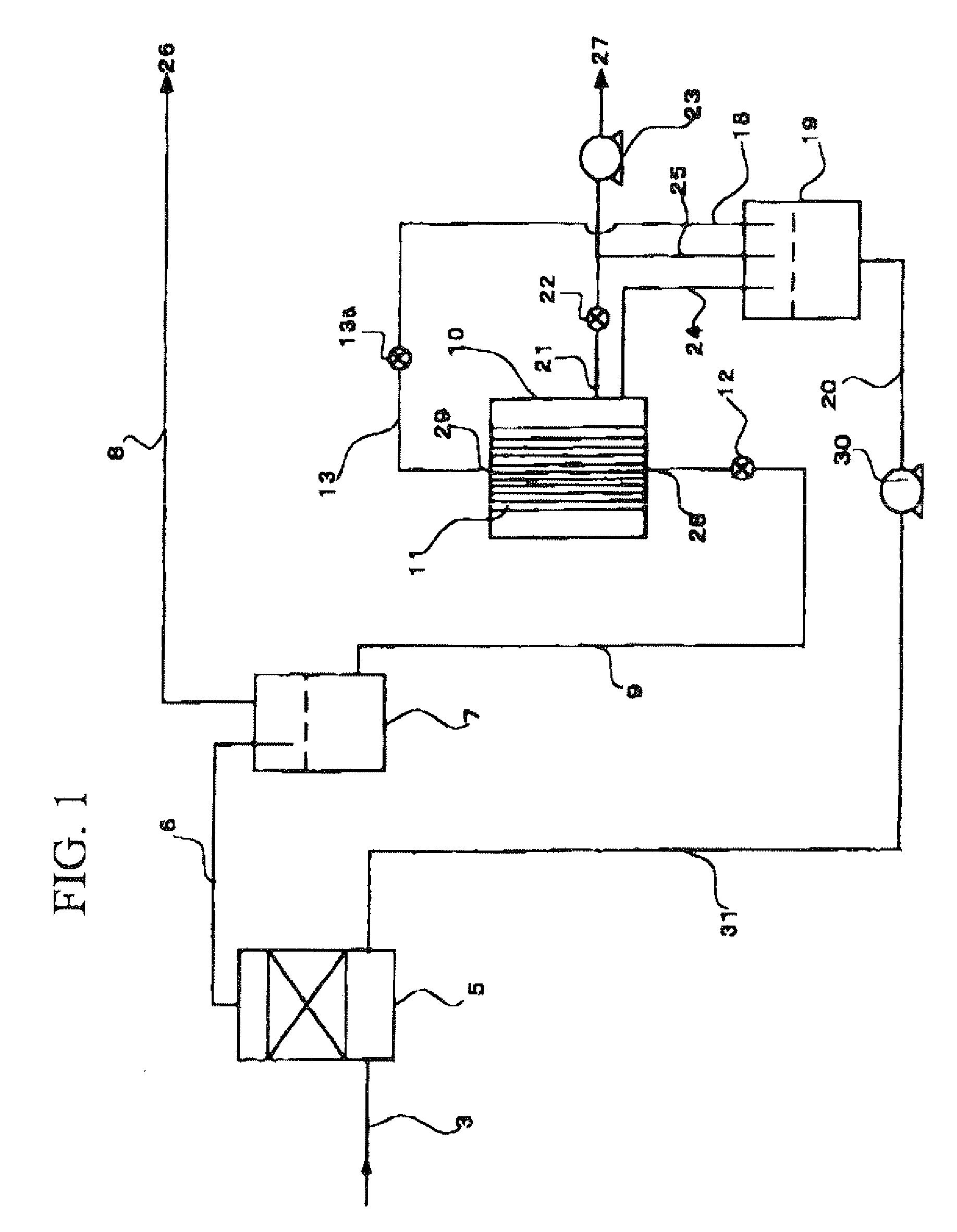
[0095]In Example 1, comparison test of the concentration of methane concentrated by mixers of 3 different kinds of absorption systems was carried out by using the methane separation apparatus of a one stage separation system shown in FIG. 1.

[0096]FIG. 5 is a comparison chart of concentrations of the concentrated methane obtained by conducting methane separation from the absorbing liquid that absorbed carbon dioxide using mixers of 3 different absorption systems. The longitudinal axis indicates the concentration of concentrated CH4 (%) that is separated. The transverse axis indicates the required membrane area (m2 / (N1 / min)), which is the surface area of a permeable membrane per unit flow rate of a biogas to be treated. More specifically, the required membrane area is defined by the following equation: Required membrane area=(surface area of permeable membrane installed in membrane module)[m2] / (biogas treatment flow rate)[N1 / min], and the lower value of required membrane area means hi...

examples 2 to 5

[0100]In Examples 2 to 5, separation and purification of methane were carried out using the methane separation apparatus of a one stage separation system shown in FIG. 1.

[0101]Tables 1 to 4 show details of the respective conditions, in which Examples 2 to 5 were conducted.

TABLE 1Biogas treatment flow rateNl / min0.67Degree of vacuumkPaG−90.2CH4 concentration%98.4DEA temperature° C.29CH4 recovery rate%99.5Membrane aream20.062Required membrane aream2 / (Nl / min)0.09Flow rate of permeatingL / m2 · min40.6liquid per membrane areaGas / liquid ratio (Nl / L)0.27Absorbing liquid3 mol / l-DEAHollow fiber materialPolyethyleneMembrane effective length47φ0.7 mm[cm]Pore size [nm]250Membrane filling rate0.096[m2 / m2]

TABLE 2Biogas treatment flow rateNl / min0.67Degree of vacuumkPaG−91.3CH4 concentration%98.2DEA temperature° C.29CH4 recovery rate%99.6Membrane aream20.062Required membrane aream2 / (Nl / min)0.09Flow rate of permeatingL / m2 · min28.4liquid per membrane areaGas / liquid ratio (Nl / L)0.27Absorbing liquid3 mo...

example 6

[0105]In Example 6, the methane separation apparatus according to the present invention was compared with the apparatus of a conventional methane purification system in terms of gas separation performance, purification cost, and the like.

[0106]Table 5 compares the methane separation apparatus according to the present invention with the apparatus of a conventional methane purification system in terms of gas separation performance, purification cost, and the like,

TABLE 5Comparison of each systemDry membraneChemicalseparationabsorption methodMembrane / absorptionItemPSA processprocess(diethanolamine)hybrid methodOperatingNormal pressure0.6 to 0.7 MPaGNormal pressureNormal pressurepressure(desorption(desorption−90 kPaG)−90 kPaG)CH490%90%90%90%concentrationCH4 recovery90% (CH470% (CH4≈100% (no≈100% (norateconcentrationconcentrationdependence ondependence on90%)90%)CH4 concentration)CH4 concentration)Required21202017power [kW]Power unit0.390.480.330.28consumption[kWh / m3]N.B.)Calculated by a...


PUM


Abstract

A methane separation method of the present invention at least includes: mixing the biogas and an absorbing liquid that absorbs carbon dioxide in a mixer so as to form a mixed fluid of a gas-liquid mixed phase; introducing the mixed fluid into a first gas/liquid separator so as to separate the mixed fluid through gas/liquid separation into methane and a CO2-absorbed liquid formed due to an absorption of the carbon dioxide by the absorbing liquid; recovering methane separated in the first gas/liquid separator; and supplying the CO2-absorbed liquid through a supply port of a membrane module comprised of a container and a plurality of hollow fiber permeable membranes built therein to inside of the membranes so as to make the CO2-absorbed liquid permeate the permeable membranes, and lowering a pressure outside the permeable membranes to a level lower than that inside the permeable membranes.

Description

TECHNICAL FIELD[0001]The present invention relates to a methane separation method that separates methane from biogases such as a natural gas that has methane as its major component and is generated from underground due to the anaerobic fermentation by organisms, an underground fermentation gas produced by a natural anaerobic fermentation due to an underground burial of industrial and domestic wastes, and an artificial fermentation gas generated artificially and discharged from an anaerobic fermentation process, a methane separation apparatus that carries out the method, and a methane utilization system that is capable of supplying the separated methane to the energy market.[0002]Priority is claimed on Japanese Patent Application No. 2006-103665, filed Apr. 4, 2006, the content of which is incorporated herein by reference.BACKGROUND ART[0003]There are cases where a large amount of carbon dioxide and water that cannot be used as a heat energy source are contained in the gases constitu...

Claims


Application Information

Patent Timeline
IPC IPC(8): C07C7/12B01D59/12
CPCB01D3/101B01D19/0031B01D53/1425B01D53/1487B01D53/22B01D63/04B01D2258/05C10L3/10C10L3/102Y02C10/06Y02C10/10B01D63/043C07C7/11B01D2257/504Y02C20/40Y02P70/10
Inventor TOMIOKA, TAKAFUMIABE, TOSHIYUKISAKAI, TORUMANO, HIROSHIOKABE, KAZUHIRO
Owner TAIYO NIPPON SANSO CORP
Why Eureka
Try Eureka