
Process for Producing Propylene and Aromatic Hydrocarbons, and Producing Apparatus Therefor

a technology of propylene and aromatic hydrocarbons, which is applied in the direction of hydrocarbon oil treatment products, bulk chemical production, physical/chemical process catalysts, etc., can solve the problems of high production cost, high production cost, and high production cost, and achieves easy production ratios, efficient and stable production, and the effect of promoting equipment soiling

Active Publication Date: 2010-01-28
ASAHI KASEI KK
View PDF5 Cites 6 Cited by
  • Summary
  • Abstract
  • Description
  • Claims
  • Application Information

AI Technical Summary

Benefits of technology

[0064]According to the producing process of the present invention, propylene and aromatic hydrocarbons can be efficiently and stably produced from olefinic hydrocarbon feedstock, and the production ratios thereof can be easily varied as necessary.
[0229]The producing process according to the present invention is applicable in the field of process for producing propylene and aromatic hydrocarbons because it has the effects of allowing propylene and aromatic hydrocarbons to be efficiently and stably produced and also allowing changes in the yield structure by easy methods in the process for producing propylene and aromatic hydrocarbons from a hydrocarbon feedstock containing olefins

Problems solved by technology

Thermal cracking has been widely used for obtaining propylene and aromatic hydrocarbons from hydrocarbon feedstock, but by its very nature thermal decomposition requires severe reaction conditions, and a common by-product is methane, which is difficult to use as petrochemical feedstock.
Moreover, the product yields of propylene and other olefins and benzene, toluene and other aromatic hydrocarbons as percentages of the decomposition product are generally limited, and the yield structure is not sufficiently flexible among other problems.
Although propylene yield is improved by this method, the yield of aromatic hydrocarbons is poor.
Also, in methods for catalytic conversion of hydrocarbons using zeolite, coke accumulates on the catalyst and must be frequently removed by combustion to regenerate the catalyst, but the problem is that in the case of the acid zeolite described above, repeated regeneration operations cause permanent degradation of catalyst activity.
This poses a serious problem that must be solved if proton-type zeolites are to be used in these kinds of reactions.
Moreover, because the aforementioned paraffin conversion reaction is an endothermic reaction, a large amount of heat must be supplied to the reaction vessel.
As a result, this method requires a complex and expensive reaction system.
However, efficient, long-term and stable production of propylene from hydrocarbon feedstock containing olefins by catalytic conversion using a catalyst containing zeolite is difficult for the following reasons.
Conversely, if the catalyst is not active enough or the contact time is too short, the propylene yield will be poor.
Because olefins are highly reactive, however, deposition of coke on the surface of the catalyst is likely to occur during catalytic conversion of the hydrocarbon feedstock containing olefins using the catalyst containing zeolite.
In continuous conversion reactions, the catalyst deteriorates due to coking (coking deterioration), and catalytic activity quickly declines.
Regeneration operations are required as described above in order to reactivate the catalyst, but after repeated regeneration operations catalytic activity can no longer be adequately restored.
As discussed above, coking is particularly likely in catalytic conversion reactions of the hydrocarbon feedstock containing olefins using catalysts containing zeolite, and regeneration degradation is also extremely likely because of the consequent need for frequent regeneration operations.
Patent Document 3 describes a method for removing the heavy fraction with a boiling point at or above that of the C8 aromatic hydrocarbons from the reaction product and recycling the C4-8 olefins back into the reaction vessel, but this method requires multiple separators to obtain the raw material for recycling, thereby complicating the equipment and operations, so there is a demand for simpler methods, but so far it has not been possible to achieve both efficiency (equipment, operating costs and yield) and stable production.
The higher the diolefin compound concentration in the hydrocarbon feedstock, the more activity deteriorates due to coke production.
Removal of diolefins from the feedstock is highly unpractical on an industrial scale because it requires that the feedstock be purified by pretreatment such as separation by distillation, partial hydrogenation or the like.
As in the propylene producing step, the biggest problems with methods of producing aromatic hydrocarbons by catalytic cyclization using a zeolite catalyst are controlling coking deterioration during the reaction and controlling regeneration (permanent) degradation that occurs when the coke on the deteriorated catalyst is removed by combustion to regenerate the catalyst.
In this method, however, the preferred method of synthesizing the zeolite is one using a seed slurry, which has low productivity, and moreover the stable production range of ZSM-5 zeolite is narrow, limiting the SiO2 / Al2O3 ratio so that the primary particles are likely to be relatively large.
According to Patent Document 4, both coking deterioration and regeneration degradation are controlled, but because the zeolite particle size is relatively large, it does not appear that coking deterioration is adequately controlled.
A zeolite with a smaller primary particle size would be preferable, but according to Patent Document 4 this results in greater accumulation of coke during the reaction, and more rapid regeneration (permanent) degradation.
These are serious obstacles to the industrial manufacture of aromatic hydrocarbons.
The catalyst used in this method is effective at resisting regeneration degradation as described above, but the problem of coking deterioration remains.
Consequently, coking deterioration is likely when the hydrocarbon feedstock contains large amounts of olefins.

Method used


Image

  • Process for Producing Propylene and Aromatic Hydrocarbons, and Producing Apparatus Therefor
  • Process for Producing Propylene and Aromatic Hydrocarbons, and Producing Apparatus Therefor
  • Process for Producing Propylene and Aromatic Hydrocarbons, and Producing Apparatus Therefor

Examples


example 1

[0179]An Na-type ZSM-5 extrudate with a SiO2 / Al2O3 molar ratio of 1200 (containing 30% by mass of SiO2 binder, 1.6 mmφ, purchased from Nikki Universal Co., Ltd., Japan) was dispersed in an 0.02 N aqueous silver nitrate solution (10 cc / g-molded zeolite), and subjected to ion-exchange treatment at 60° C. for 1 hour, a treatment that was repeated twice. This was then filtered, water-washed and dried to prepare catalyst A-1. The Ag content of catalyst A-1 as measured by fluorescent x-ray analysis was 0.22% by mass.

[0180]A Hastelloy C reactor with an inner diameter of 27 mm was filled with catalyst A-1, which was then steamed for 5 hours under conditions of temperature 650° C., steam flow rate 214 g / hr, nitrogen flow rate 400 NL / hr, and pressure 0.1 MPaG. After steaming treatment, the amount of proton of catalyst A-1 was 0.002 mmol / g as determined by liquid phase ion exchange / filtrate titration. 60 g of the steamed catalyst A-1 was packed in a Hastelloy C reactor with an inner diameter o...

example 2

[0189]60 g of catalyst A-1 that had been steamed as in Example 1 was packed in a Hastelloy C reactor with an inner diameter of 27 mm.

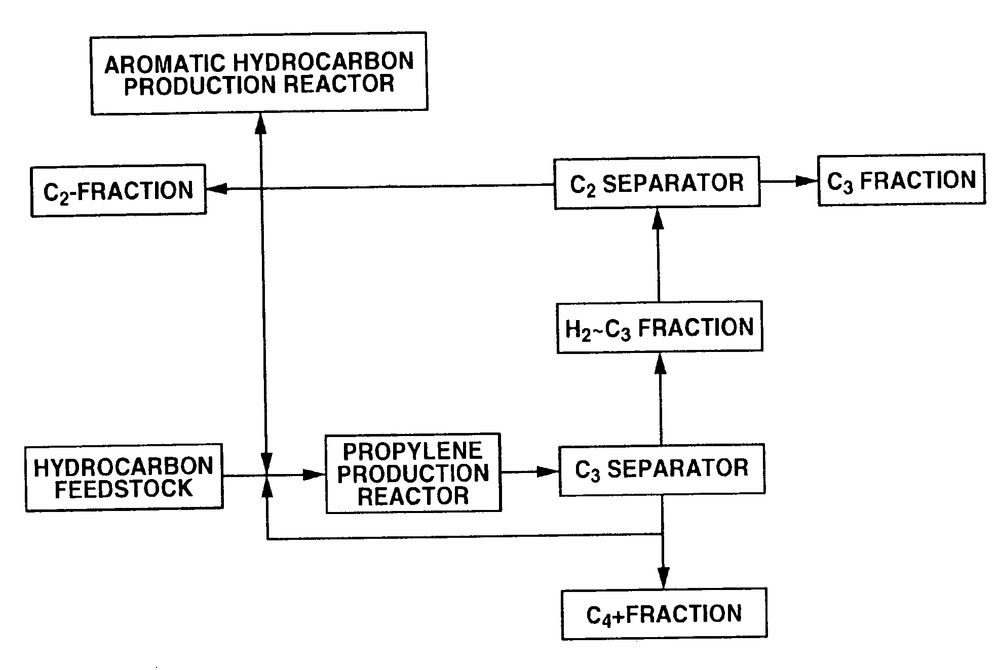
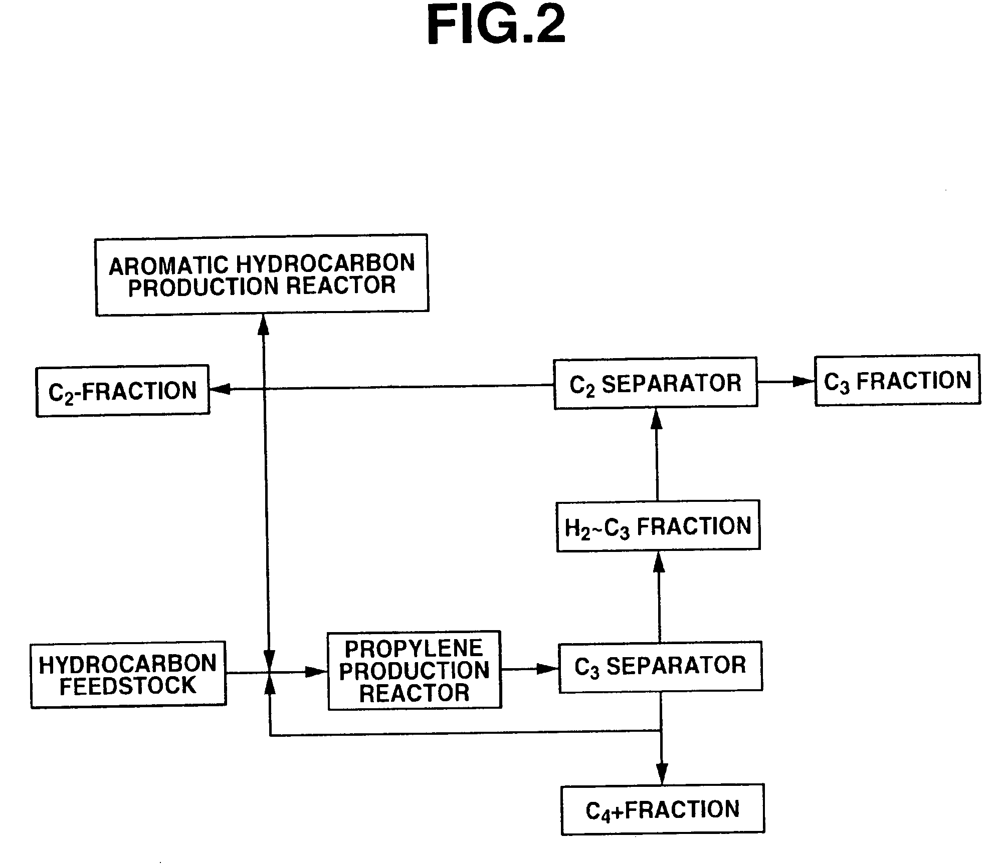
[0190]Using C4 raffinate-2 shown in Table 1 as the raw material, a propylene production reaction was performed with a reaction temperature of 550° C., a C4 raffinate-2 supply rate of 220.3 g / hr, a recycled C4+fraction supply rate of 139.7 g / hr (WHSV=6 hr−1), a steam supply rate of 108 g / hr and a reaction pressure of 0.1 MPaG, the resulting reaction product was supplied to a distillation column and separated into a H2˜C3 fraction and a C4+fraction, and about 56% of the C4+fraction was recycled back to the reactor.

[0191]The propylene production reaction was continued for 2 days, after which the catalyst was regenerated under the following conditions: regeneration temperature 500 to 550° C., regeneration pressure 0.5 MPaG, nitrogen+air flow rate 1008 NL / hr, oxygen concentration 1 to 5 vol %, regeneration time 10 hours. The yields based on C4 raffinate-2 (...

example 3

[0194]A propylene production reaction was performed under the same conditions as in Example 2 except that the C4 raffinate-2 supply rate was 279.1 g / hr, the recycled C4++fraction supply rate was 80.9 g / hr (WHSV=6 hr−1), and about 33% of the C4++fraction was recycled back to the reactor. The yields based on the C4 raffinate-2 (% by mass) are shown in Table 1. The propylene yield based on C4 raffinate-2 was 33.24% by mass 2 hours after the start of the reaction, and 31.35% by mass 48 hours after the start of the reaction. The value obtained by dividing the amount of component (% by mass) of the C6-8 aromatic hydrocarbons produced in the reactor by the hydrocarbon partial pressure [MPa] was 4.8.

[0195]An aromatic hydrocarbon production reaction was performed under the same conditions as in Example 1 except that the raw material was the C4+fraction obtained in this Example 3. The yield of C6-9 aromatic hydrocarbons was 46.3% by mass 8 hours after the start of the reaction and 45.5% by ma...


PUM

PropertyMeasurementUnit
molar ratioaaaaaaaaaa
partial pressureaaaaaaaaaa

Abstract

It is an object of the present invention to provide an improved process whereby the yield structure of the components can be varied by a simple method, and the products can be produced stably and efficiently in a process for producing propylene and aromatic hydrocarbons from a hydrocarbon feedstock containing C4-12 olefins using a medium pore diameter zeolite-containing catalyst. A process for producing is disclosed which comprises a propylene production step wherein a specific zeolite catalyst is used to remove a C4+ hydrocarbon component from a reaction mixture, and part of the hydrocarbon component is recycled as necessary without modification, and an aromatic hydrocarbon production step wherein all or a part of the C4+ hydrocarbon component is used as the raw material.

Description

TECHNICAL FIELD[0001]The present invention relates to a process for producing propylene and aromatic hydrocarbons by catalytic conversion and catalytic cyclization from a hydrocarbon feedstock, and to a producing apparatus therefor.BACKGROUND ART[0002]Thermal cracking has been widely used for obtaining propylene and aromatic hydrocarbons from hydrocarbon feedstock, but by its very nature thermal decomposition requires severe reaction conditions, and a common by-product is methane, which is difficult to use as petrochemical feedstock. Moreover, the product yields of propylene and other olefins and benzene, toluene and other aromatic hydrocarbons as percentages of the decomposition product are generally limited, and the yield structure is not sufficiently flexible among other problems.[0003]Patent Document 1 discloses a method wherein silver is carried on crystalline aluminosilicate zeolite in order to improve selectivity for lower olefins. Although propylene yield is improved by this...

Claims


Application Information

Patent Timeline
Patent Type & Authority Applications(United States)
IPC IPC(8): C07C4/00B01J19/00
CPCB01J29/44C10G2400/30B01J2229/186B01J2229/36C07C2/84C07C4/06C07C2529/40C07C2529/44C10G11/05C10G35/065C10G63/04B01J2229/16C10G2400/20C10G2300/4081C10G2300/1088C10G2300/4018C07C15/00C07C11/06Y02P20/52Y02P20/584C07B61/00C07C2/42
Inventor SEKIGUCHI, MITSUHIROTAKAMATSU, YOSHIKAZU
Owner ASAHI KASEI KK
Learn More