
Electrode binder, electrode, membrane-electrode assembly and polymer electrolyte fuel cell

a technology of electrolyte fuel cell and electrode, which is applied in the direction of non-aqueous electrolyte cells, cell components, electrochemical generators, etc., can solve the problems of short heat resistance of sulfonated fluorine resin having the thermoplasticity, reducing ion conductivity, and breaking of ion channel structures, so as to improve power generation performance and high durability

Inactive Publication Date: 2010-04-15
SEKISUI CHEM CO LTD
View PDF2 Cites 13 Cited by
  • Summary
  • Abstract
  • Description
  • Claims
  • Application Information

AI Technical Summary

Benefits of technology

[0021]An object of the present invention is to provide an electrode having improved power generation performance and high durability, and a fuel cell having such an electrode with the same.Means for Solving the Problems
[0034]According to the present invention, an electrode having improved power generation performance and high durability, and a fuel cell having such an electrode with the same, are provided.

Problems solved by technology

However, the sulfonated fluorine resin having the thermoplasticity has a problem of being short of heat resistance at the time of operating the polymer electrolyte fuel cell.
Specifically, the sulfonated fluorine resin exerts proton conductivity in such a manner that ion channels are formed therein by coagulation of sulfone groups; however, the sulfonated fluorine resin has a defect of being plastically deformed at a specific temperature or more because of having the thermoplasticity, resulting in the breakage of an ion channel structure.
Therefore, in the sulfonated fluorine resin, the plastic deformation occurs in a short time at approximately 130° C. of a glass transition temperature (Tg) or more, and gradually occurs even in a temperature range from 100 to 130° C., and ion conductivity is lowered, whereby it is difficult to maintain high fuel barrier property.
However, the above-mentioned sulfonated fluorine resin membrane has extremely high affinity with the methanol, and accordingly, has had a serious problem that the sulfonated fluorine resin concerned largely swells by absorbing the methanol, causes a so-called methanol crossover in which the methanol permeates the swelled proton conducting membrane to then leak out to the cathode side, resulting in that the output of the fuel cell is largely lowered.
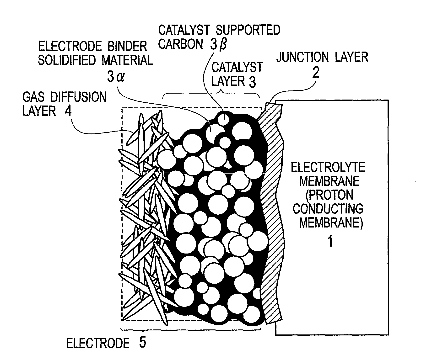
In case of using the electrode composed of the electrode binder solidified material of the sulfonated fluorine resin described above, a softening due to heat and a swelling due to methanol absorption of the sulfonated fluorine resin are large, and accordingly in the operation under high temperatures, and / or in case of using a fuel of a relatively high methanol concentration, there have been problems, for example, a sufficient power generation performance can not be obtained or durability is deteriorated.
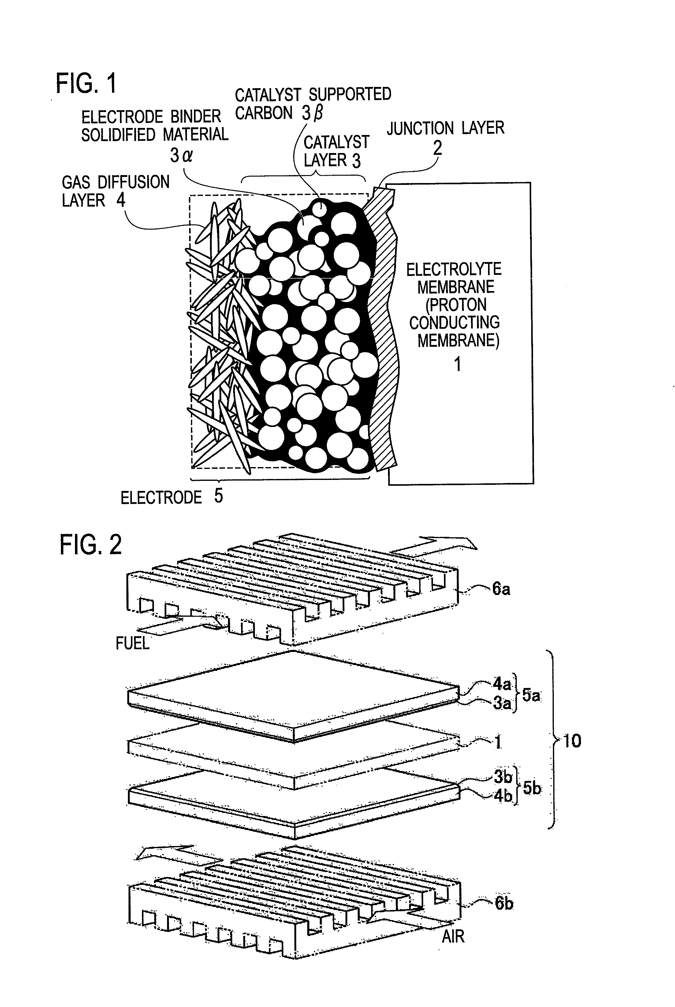
However, when even higher power generation performance is required to be obtained, as an acid component, whether a material has a specific property inherent in an inorganic material or inherent in an organic material, when the material has a large molecular weight as well as an almost single molecular weight distribution, then, since an acid component is difficult to enter inside of a secondary agglomerate (agglomerate) of catalyst supported carbon composing the electrode, a utilization efficiency of catalyst such as platinum and the like is insufficient, whereby problems such as an output decrease and the like have been produced.
Moreover, in the proton conducting membrane having the silicon-oxygen cross-linked structure, intermolecular force of a silicon-carbon bond in the membrane to the peripheries thereof is somewhat weaker than that of the silicon-oxygen bond, and impact resistance of this proton conducting membrane to an external pressure derived from a humidity change, sudden swelling and the like is sometimes low.
Therefore, for example, in the case of using a certain type of the organic silicon compound as a material of the membrane-electrode assembly for which high proton conductivity under high and low temperature conditions is required, performance deterioration in the proton conductivity and the fuel barrier property, which is caused by temperature variations, sometimes occurs.

Method used


Image

  • Electrode binder, electrode, membrane-electrode assembly and polymer electrolyte fuel cell
  • Electrode binder, electrode, membrane-electrode assembly and polymer electrolyte fuel cell
  • Electrode binder, electrode, membrane-electrode assembly and polymer electrolyte fuel cell

Examples


example 1

1-1. Fabrication of Gas Diffusion Layer

[0174]A porous conductive sheet (TGP-H-060, made by Toray Industries Inc.; Thickness: 190 μm) was impregnated into an aqueous solution of Neoflon ND-1 (made by Daikin Industries Ltd.), and the impregnating was done repeatedly until its weight reaches to 10 to 15 wt %. Thereafter, a resultant thus obtained was heated at 300° C. for 30 minutes (water-repelling treatment) . . . . S111

1-2. Production of Catalyst Ink

[0175]2.0 g of poly(2-acrylamide-2-methylpropane sulfonic acid) (in which a 15% aqueous solution made by Sigma-Aldrich Corporation was diluted by water to 2.5%), 0.3 g of catalyst supported carbon (for the cathode, platinum supported carbon: TEC10E50E made by Tanaka Kikinzoku Kogyo K. K.; Pt 48%, for the anode, platinum-ruthenium supported carbon: TEC61E54 made by Tanaka Kikinzoku Kogyo K. K.; Pt 30% Ru 23%, were used) were mixed. In the mixing, an ultrasonic homogenizer was used.

[0176]0.6 g of tetramethoxysilane was added to the mixture...

example 2

2-1. Fabrication of Gas Diffusion Layer

[0180]A diffusion layer was fabricated in a similar way to S111 of Example 1.

2-2. Production of Catalyst Ink

[0181]2.0 g of the poly(2-acrylamide-2-methylpropane sulfonic acid) (in which a 15% aqueous solution made by Sigma-Aldrich Corporation was diluted by water to 2.5%), 1.0 g of poly(styrene sulfonic acid) (in which a 18% aqueous solution made by Sigma-Aldrich Corporation was diluted by water to 2.5%), 0.3 g of the catalyst supported carbon (for the cathode, platinum supported carbon: TEC10E50E made by Tanaka Kikinzoku Kogyo K. K.; Pt 48%, for the anode, platinum-ruthenium supported carbon: TEC61E54 made by Tanaka Kikinzoku Kogyo K. K.; Pt 30% Ru 23%, were used) were mixed. In mixing, the ultrasonic homogenizer was used.

[0182]0.6 g of the tetramethoxysilane was added to the mixture described above, followed by mixing using the ultrasonic homogenizer. Furthermore, 0.5 g of the isopropyl alcohol was added to the resultant, followed by mixing u...

example 3

3-1. Fabrication of Proton Conducting Membrane

[0186]0.12 g of water and 0.060 g of triethylamine were dropped into a liquid obtained by mixing 4.07 g of a copolymer (X-41-1805, made by Shin-Etsu Chemical Co., Ltd.) of 3-mercaptopropyl trimethoxysilane and tetraethoxysilane and 1.0 g of the tetraethoxysilane with each other. A resultant solution was stirred at the room temperature for 20 minutes until becoming transparent, and was thereafter developed on a fluorine film. On this solution, a polyethylene-made porous material (average pore diameter: 0.5 μm; thickness: 50 μm; cut into a square with a side of 10 cm) was covered, and the porous material was impregnated with this liquid. The liquid was impregnated into the porous material by using a polyethylene-made pallet so as not to cause unevenness. Thereafter, such a membrane obtained after the impregnation was covered with a fluorine resin film, and an applicator was allowed to level this resultant from the above so that a membrane ...


PUM

PropertyMeasurementUnit
temperatureaaaaaaaaaa
Tgaaaaaaaaaa
particle sizeaaaaaaaaaa

Abstract

An electrode which can be used in a fuel cell having improved power generation performance and high durability, and a fuel cell having such an electrode, are provided. An electrode having catalyst layers arranged on both surfaces of an electrolyte membrane, wherein the electrode is characterized in that an electrode binder used for constituting the catalyst layers contains a cross-linked compound (X) having a silicon-oxygen bond, a polymer material (Y) containing an acid group, and an aqueous dispersion (Z) containing a thermoplastic resin.

Description

TECHNICAL FIELD[0001]The present invention relates to an electrode binder, an electrode and a membrane-electrode assembly, which can be used in a fuel cell, and a polymer electrolyte fuel cell thereof.BACKGROUND ART[0002]Fuel cells are classified into a phosphoric acid one, a molten carbonate one, a solid oxide one, a polymer electrolyte one and the like based on types of electrolytes composing the fuel cells. Among them, with regard to the polymer electrolyte fuel cell (hereinafter, referred to as a “PEFC”), a device thereof is small and an output thereof is high in comparison with the fuel cells of the other modes. Accordingly, the PEFC is placed as a system that plays a dominant role in the next generation. The PEFC is expected to serve as a fuel cell for small-scale on-site power generation, for a power source of a movable body such as a vehicle, for a portable instrument, or for the like.[0003]In a basic structure of the PEFC, gas diffusion electrodes on which a catalyst such a...

Claims


Application Information

Patent Timeline
Patent Type & Authority Applications(United States)
IPC IPC(8): H01M4/00
CPCH01M4/8652H01M4/8807H01M4/8825H01M4/926Y02E60/523H01M8/1011H01M8/1027H01M8/1037H01M8/1004Y02E60/50H01M8/10H01M8/02H01M4/86
Inventor KONNO, YOSHIHARUMIYAMA, TOSHIHITONAKAJIMA, HIDEYASUKANOH, MASASHI
Owner SEKISUI CHEM CO LTD
Learn More