Electrolyte membrane and fuel cell using the same (as amended)

a technology of electrolyte membrane and fuel cell, which is applied in the direction of fuel cells, composite electrolytes, electrochemical generators, etc., can solve the problems of significant reduction in power generation performance, significant decline in cell performance, and decline of proton conductivity, so as to increase the water absorbing capacity of the cathode side, the effect of low humidification operation

Inactive Publication Date: 2010-08-05
TOYOTA JIDOSHA KK
View PDF8 Cites 7 Cited by
  • Summary
  • Abstract
  • Description
  • Claims
  • Application Information

AI Technical Summary

Benefits of technology

[0022]According to the reinforcing-membrane-type electrolyte membrane of the present invention and the fuel cell utilizing the same, compared with a conventional reinforcing-membrane-type electrolyte membrane which has the same thickness and includes a reinforcing membrane in the middle part in the thickness direction, or with a reinforcing-membrane-type electrolyte membrane in which multiple numbers of reinforcing membranes with the same thickness and porosity are arranged in a membrane, it is possible to increase the concentration gradient of water by actively forming a water content gradient in the membrane, in which water content is low at the anode side and is high at the cathode side during power generation. Thereby, a water back-diffusion effect which causes water to move from the cathode-side to the anode-side can be enhanced so that a dry-up which tends to take place in a low humidification operation can be effectively prevented. Moreover, since the capability to absorb the product water produced at the cathode-side catalyst layer will increase, a flooding at the cathode-side electrode which tends to take place during a high humidification operation can be prevented.
[0023]Further, as a result of the increase of the water absorbing capability of cathode side in a reinforcing-membrane-type electrolyte membrane, it becomes possible to absorb the product water at the cathode-side catalyst layer during power generation, and freezing of water which tends to take place in a catalyst layer at low temperatures can be prevented. As the result of this, the low-temperature start-up performance of the fuel cell is improved as well.

Problems solved by technology

In a PEFC, a thin membrane of perfluorosulfonic acid polymer (Nafion® membrane, DuPont, USA), which is a fluorine-based electrolyte resin (ion exchange resin), is mainly used as the electrolyte membrane (see Patent Document 1 etc.) Moreover, since a thin membrane made up of an electrolyte resin alone does not provide enough strength, a reinforcing-membrane-type electrolyte membrane is used, in which an expanded porous reinforcing membrane (for example, a thin membrane formed by expanded PTFE or polyolefin resin, etc.) is impregnated with an electrolyte resin dissolved in a solvent and dried (Patent Document 2 and Patent Document 3, etc.)
On the other hand, in fuel cells of recent years, for the purpose of system simplification and cost reduction, there is growing need for the operation at lower humidification levels; however, an operation at a low humidification level will lead to a decline of proton conductivity, which will result in a significant reduction in the power generation performance compared with at a high humidification level.
When the anode side becomes dry, the proton conductivity of the electrolyte of the anode side decreases and also the resistance of the entire cell increases, leading to a significant decline in the cell performance.

Method used


Image

  • Electrolyte membrane and fuel cell using the same (as amended)
  • Electrolyte membrane and fuel cell using the same (as amended)
  • Electrolyte membrane and fuel cell using the same (as amended)

Examples


example 1

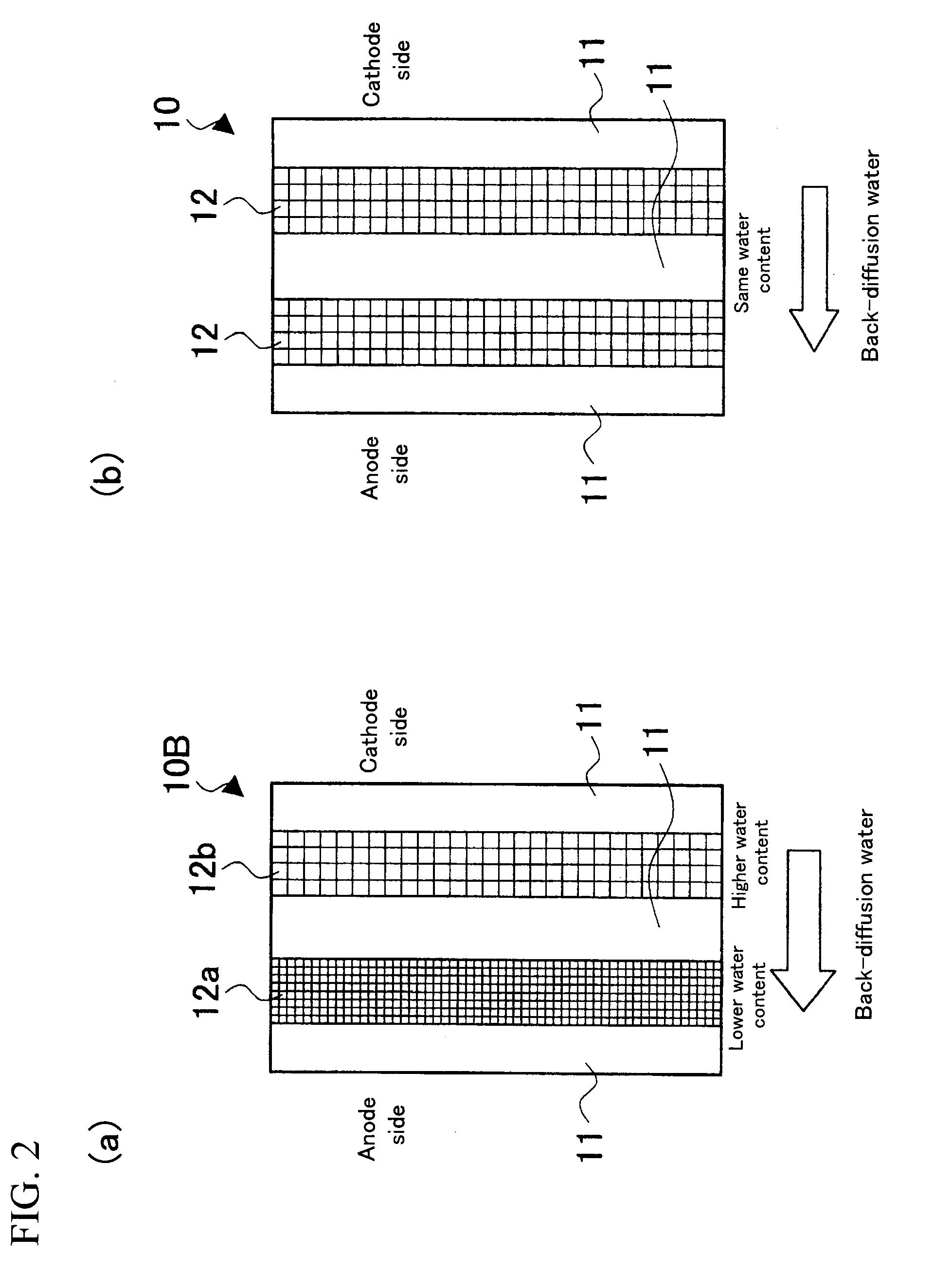
[0048](1) PTFE was expanded in two axis directions to prepare a first expanded porous reinforcing membrane 12a of a resin equivalent tensile strength of 200 Mpa and a porosity of 60%, and a second expanded porous reinforcing membrane 12b of a resin equivalent tensile strength of 100 Mpa and a porosity of 80%.

[0049](2) A solution of electrolyte resin (“DE2020”, a polymeric solution manufactured by DuPont, whose polymer-chain ends are —SO3H) was poured onto a first porous reinforcing membrane 12a placed on a glass substrate; a second porous reinforcing membrane 12b was placed thereon; and further the aforementioned solution of electrolyte resin was poured thereto. The mixture was dried at 70° C. for 1 hour to obtain a reinforcing-membrane-type electrolyte membrane having a configuration shown in FIG. 2(a) and a thickness of about 30 μm.

example 2

[0050](1) Expanded porous reinforcing membranes 12a and 12b similar to those of Example 1 were prepared.

[0051](2) Precursor resin of electrolyte resin (“NE111F”, a polymer manufactured by DuPont, whose polymer-chain ends are —SO2F) was extruded by an extrusion machine to obtain a thin membrane of a thickness of about 8 μm.

[0052](3) Three sheets of the aforementioned electrolyte resin precursor thin membranes and expanded porous reinforcing membranes 12a and 12b were alternately laminated so as to obtain a layer structure shown in FIG. 2(a), which were subjected to an impregnation treatment at a pressure of 5 kg / cm2 under a vacuum environment of 230° C. to obtain a transparent membrane.

[0053](4) The above described transparent membrane was subjected to hydrolysis with a mixed solution of 1 mol / L sodium hydroxide aqueous solution and alcohol, and thereafter polymer-chain ends were converted to an acid group (—SO3H) with 1 mol / L sulfuric acid aqueous solution.

[0054](5) The membrane imp...


PUM

PropertyMeasurementUnit
operating temperatureaaaaaaaaaa
porosityaaaaaaaaaa
porosityaaaaaaaaaa

Abstract

In a fuel cell 1 including a membrane electrode assembly 2 which includes a reinforcing-membrane-type electrolyte membrane 10A, a dry-up on the anode side is suppressed by actively forming a water content gradient in the electrolyte membrane to enhance water back-diffusion effect from the cathode side to the anode side. For that purpose, two sheets of expanded porous membranes 12a and 12b having different porosities are buried, as reinforcing membranes, in electrolyte resin 11 to obtain the reinforcing-membrane-type electrolyte membrane 10A. The reinforcing-membrane-type electrolyte membrane 10A is used to form the membrane electrode assembly 2, which is sandwiched by separators 20 and 30 such that the side of a reinforcing membrane 12b with a larger porosity becomes the cathode side, thus obtaining the fuel cell 1. When one sheet of the reinforcing membrane is buried, the reinforcing membrane is offset to the anode side to be buried in the electrolyte resin.

Description

TECHNICAL FIELD[0001]The present invention relates to an electrolyte membrane for a fuel cell, and a fuel cell including the same.BACKGROUND ART[0002]As a type of fuel cell, a polymer-electrolyte fuel cell (PEFC) is known. Compared with other types of fuel cells, a PEFC has a lower operating temperature (about −30 to 120° C.) and potential for reductions in cost and size, and therefore is expected to be a power source for automobiles, and others.[0003]As shown in FIG. 5, a PEFC 1 is configured such that a membrane electrode assembly (MEA) 2, which is a principal component, is sandwiched by an anode-side separator 20, which includes a fuel (hydrogen) gas channel 21, and a cathode-side separator 30, which includes an air (oxygen) channel 31, to form a fuel cell 1 called as a single cell. The membrane electrode assembly 2 has a structure in which an anode-side electrode 15a, which is made up of a catalyst layer 13a and a gas diffusion layer 14a of anode side, is laminated on one side o...

Claims


Application Information

Patent Timeline
Patent Type & Authority Applications(United States)
IPC IPC(8): H01M8/10
CPCH01M8/04119H01M8/1058Y02E60/521H01M2300/0082H01M2300/0088H01M8/1067Y02E60/50
Inventor INOUE, KYOJIROTAKESHITA, SHINYA
Owner TOYOTA JIDOSHA KK
Why Eureka
Try Eureka