Biosensor

a biosensor and electrode technology, applied in the field of biosensors, can solve the problems of constant changes in the electrical interaction between the cell and the electrode assembly, the difficulty of achieving good sample-electrode interaction, and the motility and structural plasticity of such cells, so as to reduce the resistance between the patch clamp electrode and the reference electrode, and improve the likelihood of contact

Inactive Publication Date: 2010-09-30
AGENCY FOR SCI TECH & RES
View PDF2 Cites 59 Cited by
  • Summary
  • Abstract
  • Description
  • Claims
  • Application Information

AI Technical Summary

Benefits of technology

[0024]Apart from providing conventional patch clamp functions, the patch clamp electrode and reference electrode also serves several other functions. Firstly, it detects if a cell positions on or seals the aperture properly. Before a cell position on the aperture, the resistance between a patch clamp electrode and reference electrode is low because electrolyte solution is conductive. When a cell positions itself over or seals the aperture, the resistance will increase. If sealed properly, the resistance should be as high as in the range of around 1 giga-ohms or more, so that the patch clamp test can be successfully reliable performed. A second function of the electrodes is to generate non-uniform electrical field around apertures to assist cells to flow to apertures because of electrophoretic effect. Thirdly, the electrodes characterize electrical properties of trans-membrane ion channels or of ionotropic receptors (for example by voltage clamp techniques). For example, after the membrane of a cell is ruptured, an electrical potential difference is applied across the membrane which contains the respective ion channel or ion channels by patch clamp electrode and reference electrode and simultaneous the current necessary for maintaining this difference is analyzed. In this way, the change in electrical properties of transmembrane ion channel in response to various test stimuli can be measured.
[0025]The sensing electrode may have any suitable shape, such as a regular solid elliptical shape or a solid rectangular shape, in particular a solid circular shape or a solid square shape. Alternatively, the sensing electrode may have a regular ring (annular) shape wherein the first opening through which suction force is exerted is located within the ring-shaped sensing electrode. An electrode having such a shape is also known as ring electrodes. It is also possible to use irregular shapes, as long as it provides sufficient contact with the biomolecule to be tested. Apart from sensing electrodes which are unitary-shaped, i.e. comprising a single element, a further alternative which has been contemplated includes a sensing electrode which comprises several individual sensing electrode elements arranged around the first opening of a channel. The sensing electrode elements may have any suitable shape. To improve the likelihood of contact between the biomolecule and the sensing electrode in this alternative, 4 or more sensing electrode elements may be arranged around the first opening of the channel.

Problems solved by technology

However, the electronic supervision of neuronal nets in these devices requires a precise placement of the neurons on the sensor.
A problem encountered in implementing such an arrangement is the establishment of good physical interaction (and thus a stable electrical connection) between a sample and the electrode assembly.
One factor contributing to the difficulty in achieving good sample-electrode interaction is the motility and structural plasticity of such cells.
This results in constant changes in the electrical interaction between the cell and the electrode assembly.
Such a problem becomes more acute when scaling up the device to provide large scale, high testing throughputs.
Likewise, cultured neurons seldom maintain a constant position on the surface of a test device.
This neuron mobility results in continuous translocation of the neuronal cell body with respect to the electrode surface which consequently affects the sensitivity of the sensor and the accuracy of the recorded potential.
In addition to this problem, a large fraction of cultured neurons often does not form secure physical contact with the sensing device and, thus, a functional contact with the surface electrodes is not established.
It has been previously reported that such a phenomenon only has a certain statistical chance of occurring, and is consequently not sufficiently reliable for cell monitoring purposes.
However, in actual practice and in a multi-transistor array, it becomes impractical to manually place individual neurons within micro-scale pillars.
However, no dedicated structure is provided on the sensor for immobilising the cell samples.
A drawback of the above devices is the difficulty in carrying out pharmaceutical screening of drugs on individual living cells without affecting other adjacent cells.
Such an arrangement requires significant installation effort and a highly qualified operator to manually operate the experimental equipment and is subject to high failure rates.

Method used


Image

  • Biosensor
  • Biosensor
  • Biosensor

Examples


second embodiment

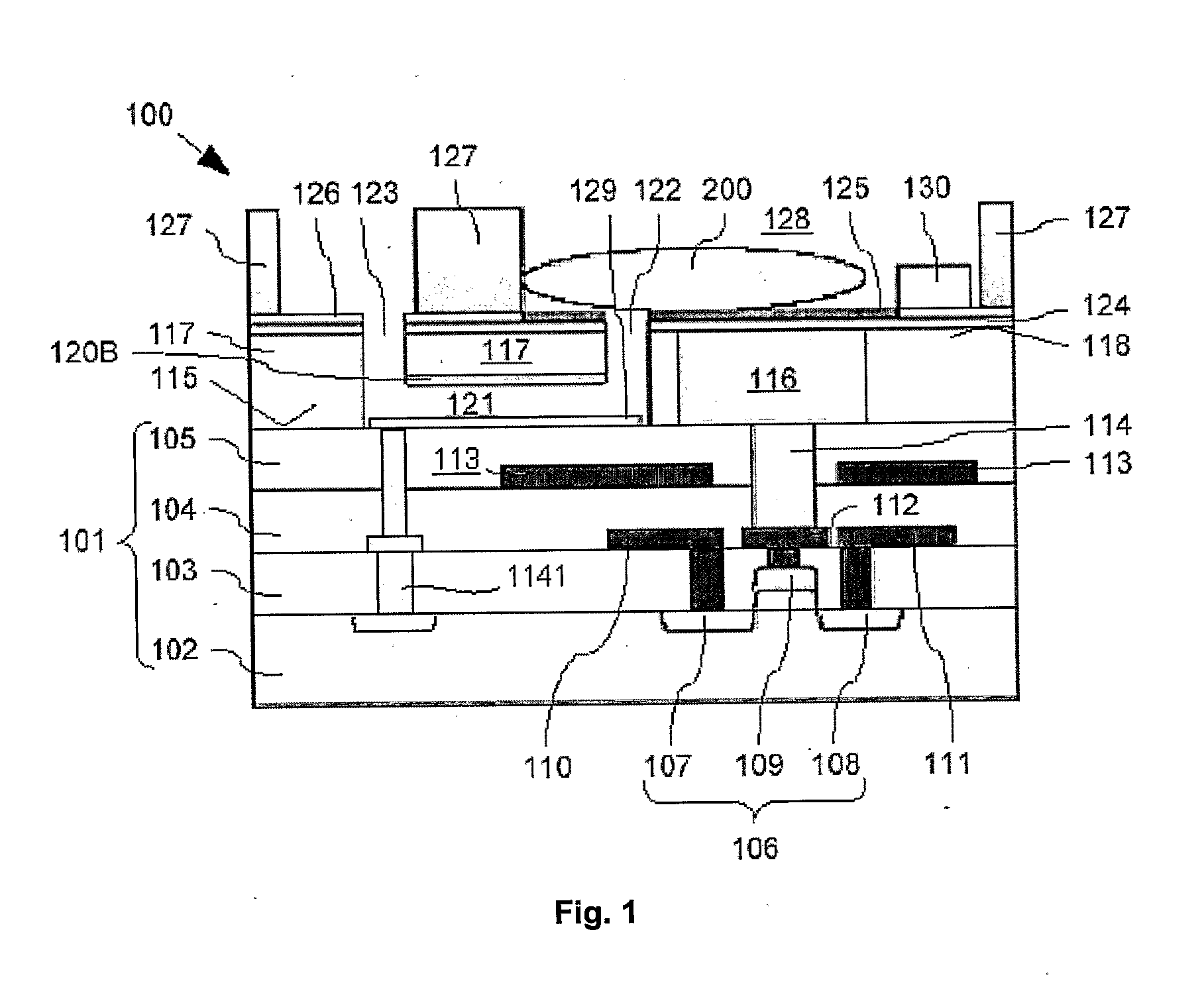
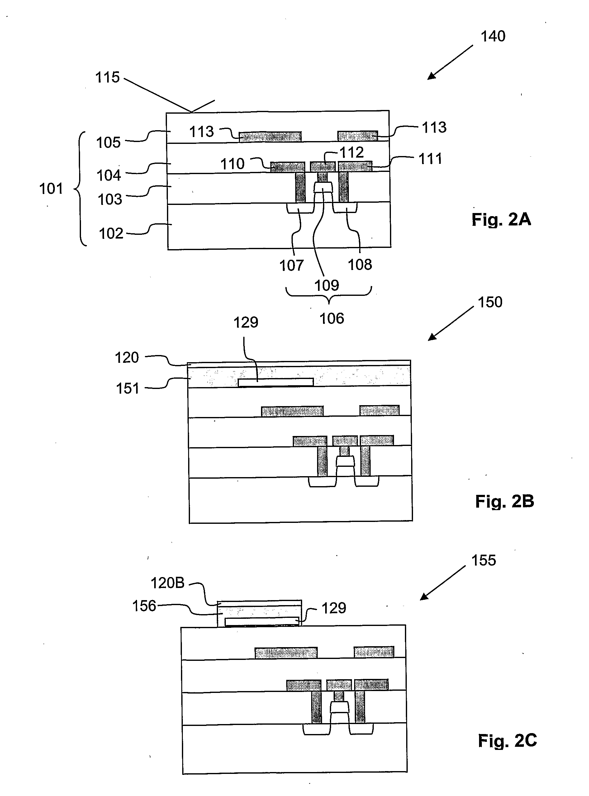
[0063]Cross-sections through the biosensor 100 according to the present invention during different production steps are now shown in FIG. 2A to FIG. 2J. Features already described with respect to FIG. 1 will not be described again here. Nevertheless, same reference signs refer to identical components.

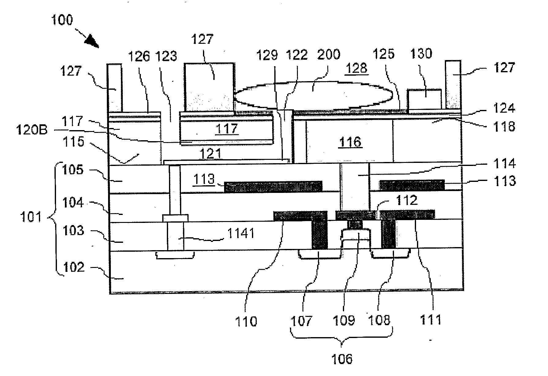
[0064]The production of the biosensor 100 is described starting at a first intermediate product. 140 shown in FIG. 2A fabricated with generally known CMOS technology such as implant, film deposition, photolithography, dry etch and CMP. This first intermediate product 140 comprises the substrate 101 with buried FET 106, buried source and drain track conductors 110, 111, buried gate lead 112, and buried screening electrode 113. As already mentioned above, the substrate 101 is bordered above the FET 106 with the substrate surface 115. This first intermediate product 140 is produced using generally known production processes, a description thereof is omitted here.

[0065]On the substrate surf...

first embodiment

[0073]For completion of the biosensor 100 (compare FIG. 2J), the ninth intermediate product 185 is wet etched such that the remaining vertically thick organic layer 156 is removed. Therefore, the channel 121 is completed, i.e. the first and second openings 122, 123 are interconnected. During this wet etch process, the patch clamp electrode 129 is not affected. Then, the bio-compatible chamber walls 127 are formed on appropriate portions of the fourth electrically insulating layer 126 from bio-compatible material by generally known formation processes. According to the present invention, polydimethylsiloxane (PDMS) is used as bio-compatible material for the bio-compatible chamber walls 127. Finally, the exposed parts of the second etch mask layer 124 which are not covered by the fourth electrically insulating layer 126 are covered with the binding layer 125. Please note that for covering the exposed parts of the second etch mask layer 124 with the binding layer 125, a selective depos...


PUM

PropertyMeasurementUnit
diameteraaaaaaaaaa
dielectric constantaaaaaaaaaa
electrically insulatingaaaaaaaaaa

Abstract

A biosensor which comprises a substrate (101) having a buried electronic sensing element and a substrate surface (124) above the buried electronic sensing element; a structured top layer (125) covering the substrate surface (124), having a top surface above the substrate surface (124), and comprising at least one stimulation and/or sensing electrode (116) and a channel (121) for holding the biomolecule by means of suction through said channel (121) arranged between the top surface (125) and the substrate surface (124), the sensing electrode (116) being electrically coupled to the electronic sensing element; wherein the top surface (125) is provided for placing a biomolecule present in a sample solution thereupon, the sensing electrode (116) is provided for sensing electrical variations in and presence of the biomolecule.

Description

[0001]The present invention relates generally to bio-molecular electronics, and more particularly to a biosensor that is used for the detection of a biomolecule, such as a living cell.BACKGROUND OF THE INVENTION[0002]Over the past few decades, due to the increasing need for efficient and reliable pre-clinical pharmaceutical drug discovery methods capable of providing a battery of regulatory genotoxicity tests, growing efforts have been channeled towards the development of biosensors that are capable of providing parallel and automated monitoring of ion channel activity in cells. Amongst the various types of biosensors that are currently in use, non-invasive biosensors for carrying out cellular and tissue-based tests have seen rapid development in recent years.[0003]Non-invasive biosensors operate on the principle that the action potential of a cell (or a cellular network) corresponds to the ion currents flowing through ion channels in the cell membrane. It is widely accepted that io...

Claims


Application Information

Patent Timeline
Patent Type & Authority Applications(United States)
IPC IPC(8): C12Q1/02G01N27/00H05K13/00
CPCG01N33/48728Y10T29/49117G01N33/5438
Inventor CHEN, XIAN TONGYU, MIN BINFENG, HAN HUALO, QUO QIANG
Owner AGENCY FOR SCI TECH & RES
Why Eureka
Try Eureka