Diaminopyrene derivative and organic el device using the same

a diaminopyrene and organic el technology, applied in thermoelectric devices, group 3/13 element organic compounds, germanium organic compounds, etc., can solve the problem of unfavorable longer wavelength of fluorescence obtained from molecular aggregates and single molecules, and achieve enhanced luminous efficiency, high luminous efficiency, and increased emission lifetime

Active Publication Date: 2011-08-11
IDEMITSU KOSAN CO LTD
View PDF12 Cites 26 Cited by
  • Summary
  • Abstract
  • Description
  • Claims
  • Application Information

AI Technical Summary

Benefits of technology

[0115]It is typically known that increase in the doping concentration may bring about concentration quenching. In this respect, since molecular aggregate is prevented by effectively introducing substituents in the diaminopyrene derivative according to the aspect of the invention, increase in the doping concentration does not bring about concentration quenching, and high luminous efficiency can be maintained.
[011...

Problems solved by technology

However, pyrene skeletons exhibit high crystallinity due to their high planarity, so that crystallization tends to progress during an amorphous thin-film st...

Method used


Image

  • Diaminopyrene derivative and organic el device using the same
  • Diaminopyrene derivative and organic el device using the same
  • Diaminopyrene derivative and organic el device using the same

Examples


synthesis example 1

Synthesis of Compound (d-15)

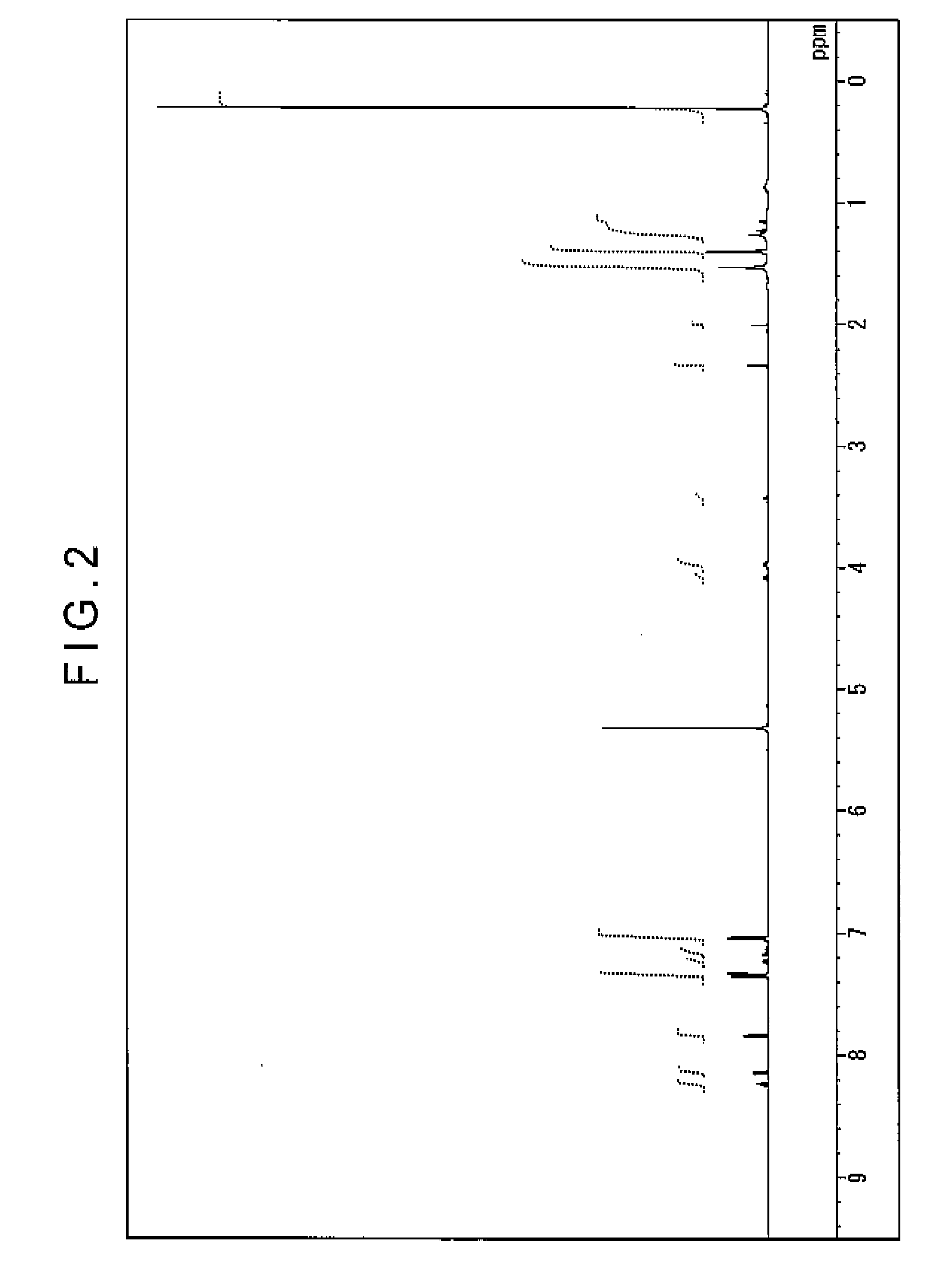
[0228]Under argon stream, 4.4 g (10 mmol) of 3,8-diisopropyl-1,6-dibromopyrene, 7.8 g (25 mmol) of bis(4-trimethyl silylphenyl) amine, 0.033 g (0.15 mmol) of palladium acetate, 0.061 g (0.3 mmol) of tri-t-butylphosphine, 2.4 g (25 mmol) of sodium t-butoxide and 100 mL of dry toluene were put into a three-neck flask of 300 mL having a cooling pipe, and stirred at 100 degrees C. for a night while heated. On completion of the reaction, the precipitated crystal were separated by filtration and cleaned with 50 mL of toluene and 100 mL of methanol. Then, 8.2 g of light yellow powder was obtained. This powder was identified as the compound (d-15) as a result of measurement of 1H-NMR spectrum and FD-MS (field desorption mass spectrum). The yield was 80%. 1H-NMR spectrum was measured with DRX-500 manufactured by Brucker Corporation (solvent of perchloromethylene).

[0229]FIG. 2 shows the measured 1H-NMR spectrum, and FIGS. 3A and 3B are magnified views of FIG. 2. FI...

synthesis example 2

Synthesis of Compound (d-8)

[0231]Under argon stream, 3.8 g (10 mmol) of 3,8-dimethyl-1,6-dibromopyrene, 6 g (25 mmol) of 4-trimethylsilyl diphenylamine, 0.033 g (0.15 mmol) of palladium acetate, 0.061 g (0.3 mmol) of tri-t-butylphosphine, 2.4 g (25 mmol) of sodium t-butoxide and 100 mL of dry toluene were put into a three-neck flask of 300 mL having a cooling pipe, and stirred at 100 degrees C. for a night while heated. On completion of the reaction, the precipitated crystal were separated by filtration and cleaned with 50 mL of toluene and 100 mL of methanol. Then, 5.6 g of light yellow powder was obtained. This powder was identified as the compound (d-8) as a result of measurement of 1H-NMR spectrum and FD-MS. The yield was 80%. The maximum absorption wavelength measured in a solution of toluene with respect to the obtained compound was 425 nm.

[0232]FIG. 4 shows the emission spectrum of the obtained compound. The maximum fluorescence wavelength was 459 nm.

example 1

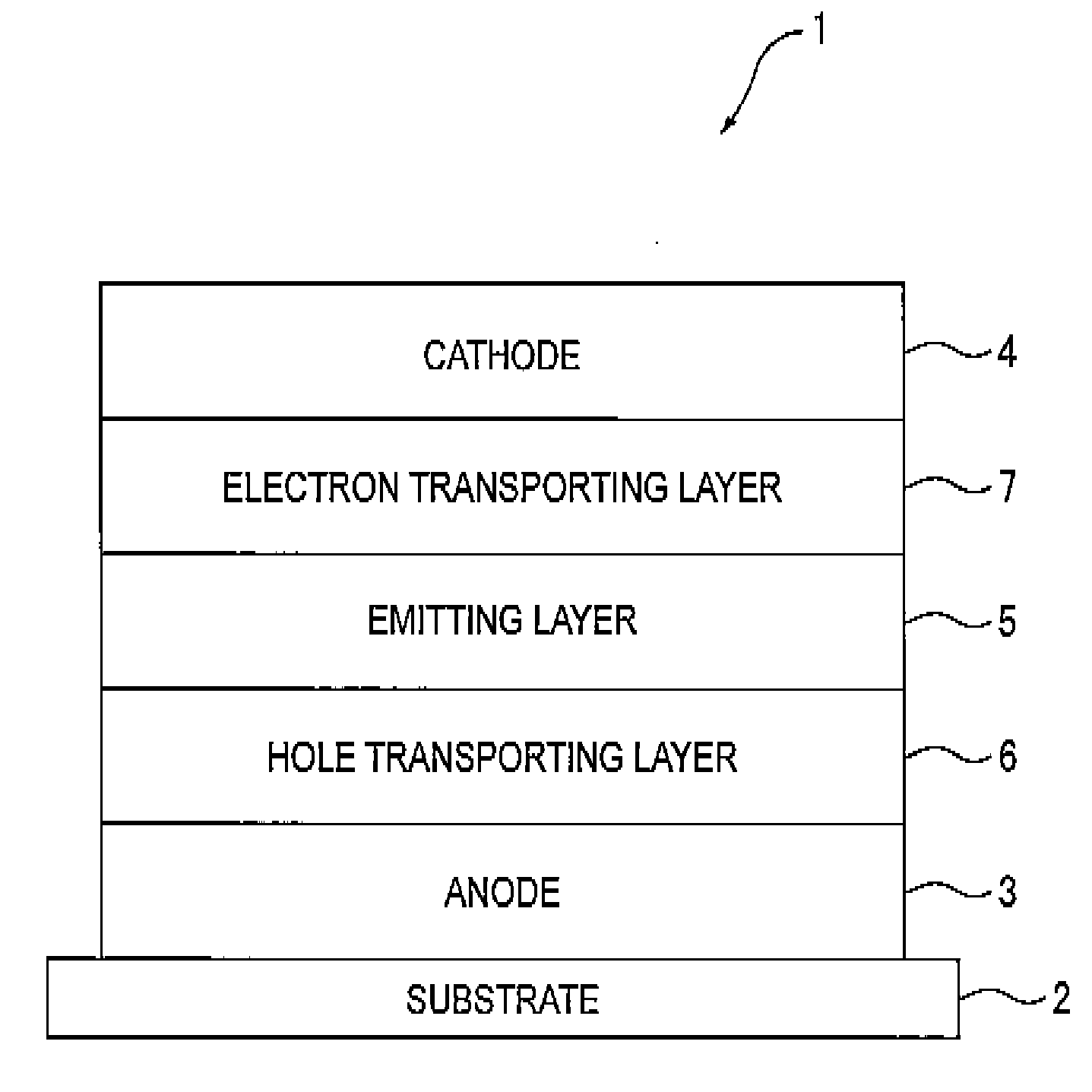
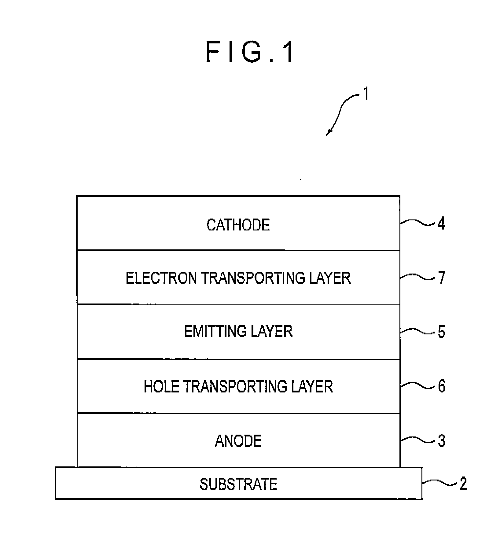
[0233]A transparent electrode made of indium tin oxide was provided onto a glass substrate (size: 25 mm×75 mm×1.1 mm) to be 120 nm thick. The transparent electrode served as the anode.

[0234]Subsequently, the glass substrate was cleaned with irradiation of ultraviolet and ozone, and mounted on a vacuum deposition equipment.

[0235]N′,N″-bis[4-(diphenylamino)phenyl]-N′,N″-diphenylbiphenyl-4,4′-diamine was initially deposited to be 60 nm thick (serving as the hole injecting layer), and then N,N,N′,N′-tetrakis(4-biphenyl)-4,4′-benzidine was deposited to be 20 nm thick (serving as the hole transporting layer). Subsequently, 10,10′-bis[1,1′,4′,1″]terphenyl-2-yl-9,9′-bisanthracene as the host and the compound (d-15) as the doping material were simultaneously deposited at a mass ratio of 40 to 2, so that a 40-nm thick emitting layer was provided.

[0236]As the electron injecting layer, tris(8-hydroxyquinolinato) aluminum was deposited on the emitting layer to be 20 nm thick.

[0237]Next, lithium ...


PUM

PropertyMeasurementUnit
Energyaaaaaaaaaa

Abstract

An organic EL device includes an emitting layer provided between an anode and a cathode. The emitting layer contains a diaminopyrene derivative represented by the following formula (1) as an emitting material for the organic EL device. The diaminopyrene derivative emits light with electrical energy.
In the formula, X and X′ each independently represent a substituent containing at least one of Ge, P, B and Si.
d and e each represent an integer of 0 to 5 while d+e≧1 is satisfied. When d is 2 or more, the plurality of X may be mutually the same or different and may be bonded together to form a saturated or unsaturated ring. When e is 2 or more, the plurality of X′ may be mutually the same or different and may be bonded together to form a saturated or unsaturated ring.

Description

CROSS-REFERENCE TO PRIOR APPLICATION[0001]This is the U.S. National Phase Application under 35 U.S.C. §371 of International Patent Application No. PCT / JP2008 / 058481 filed May 7, 2008, which claims the benefit of Japanese Patent Application No. 2007-123215 filed May 8, 2007, both of which are incorporated by reference herein. The International Application was published in Japanese on November 13, as WO2007 / 136522 A1 under PCT Article 21(2).TECHNICAL FIELD[0002]The present invention relates to a novel diaminopyrene derivative and an organic EL device using the same.BACKGROUND ART[0003]Organic EL devices, which utilize emission of organic compounds, are known.[0004]Such an organic EL device includes a plurality of organic thin films layered between an anode and a cathode. In this structure, voltage is applied between the anode and cathode. Then, holes and electrons are injected into the organic thin films respectively from the anode and cathode. The injected holes and electrons generat...

Claims


Application Information

Patent Timeline
IPC IPC(8): H01L51/54C07C211/57C07D401/10C07F7/02C07F7/30
CPCC07C211/61H01L51/5012C07C2103/50C07D213/74C07D215/24C07D215/38C07D401/12C07D471/04C07F5/027C07F7/0812C07F7/0818C07F7/30C09K11/06C09K2211/1007C09K2211/1011C09K2211/1014H01L51/0054H01L51/0058H01L51/006H01L51/0067C07C2101/14C07C2601/14C07C2603/50C07F7/081H10K85/622H10K85/626H10K85/633H10K85/654H10K50/11
Inventor FUNAHASHI, MASAKAZU
Owner IDEMITSU KOSAN CO LTD
Why Eureka
Try Eureka