Catalyst and Liquid Combination for a Thermally Regenerative Fuel Cell

a fuel cell and catalyst technology, applied in the field of energy transformation, can solve the problems of wasting heat energy available in most moving vehicles, reducing fuel efficiency, and high cost of electric energy on board moving vehicles such as trucks, cars or ships, and achieves high proton conductivity, inhibit dehydrogenation reaction, and facilitate passage of ions

Inactive Publication Date: 2011-11-10
QUEENS UNIV OF KINGSTON
View PDF2 Cites 4 Cited by
  • Summary
  • Abstract
  • Description
  • Claims
  • Application Information

AI Technical Summary

Benefits of technology

[0091]The effect of an H2 atmosphere over the liquid in the dehydrogenation reactor was also investigated, because in a working system, it is likely that the gas phase in the reactor would be primarily H2 with possibly small amounts of organic vapor, air, and / or an inert gas such as N2. By Le Chatelier's principle, the hydrogen atmosphere that will develop in the reactor should inhibit the dehydrogenation reaction by shifting the equilibrium somewhat towards the hydrogenated material. Therefore, it was also necessary to establish if the dehydrogenation catalysts being screened could afford an acceptable conversion of starting materials (for example >45%) under a H2 atmosphere in one hour. If dehydrogenation conversion is substantially less than 45% in one hour, then the catalyzed reaction may be too slow to be viable for application in vehicles at that temperature. Also of note, excess H2 may favor a hydrogenolysis reaction leading to by-product formation.
[0092]As discussed above, the fuel cell comprises a membrane electrode assembly (MEA). As one skilled in the art will know, a membrane electrode assembly comprises an anode, a cathode, and an electolytic membrane that is interposed between the anode and the cathode, and that is in functional contact with both the anode and the cathode.
[0093]In certain embodiments, an MEA includes five layers sandwiched together (see FIG. 7), where the outermost layers comprise carbon paper. This carbon paper, known as a porous transport layer, facilitates passage of ions from an external liquid and allows the ions to travel from the liquid through to the next layer. On the anodic side, the outermost carbon paper layer is in contact with a layer comprising metal (e.g., Pt or Pd on amorphous carbon). This layer is in contact with a central layer that is a polymer electrolyte membrane (PEM). In turn, the PEM is in contact with a cathodic layer comprising a metal (e.g., Pt or Pd on amorphous carbon), which in turn is in contact with the other outermost carbon paper layer.
[0094]Generation of electrical power from waste heat depends on efficient operation of a fuel cell wherein H2 is catalytically split into protons and electrons at the anode of the cell. The electrons travel through an external circuit to do work and return to the cathode, while the protons migrate from the anode to the cathode through a PEM. The protons and electrons meet fluid rich in X at the cathode, where X is catalytically hydrogenated to a fluid that is rich in XH. Effective operation of the TRFC depends on a PEM that exhibits both high proton conductivity and chemical resistivity.
[0095]In a first trial, Nafion® was initially chosen as the PEM for its high proton conductivity, although its chemical compatibility with fluids XH and X were unknown. Membrane swelling studies involved immersing pre-weighed pieces of Nafion® in different ratios of XH, X, and diluents at different temperatures, ranging from 21° C. to 90° C., and for different times, ranging from 1 h to 16 h. These studies revealed incompatibility of Nafion® with various fluid combinations. Typical effects of the fluids on Nafion® include swelling and solvent absorption (30-300% weight gain), pinhole formation, and scarring on the surface of the membrane.
[0096]Focus was then placed on preparation and subsequent swelling trials of new PEM candidates. There are many PEM candidates published in the literature and many of them are more compatible with organic solvents and liquids. For example, PEM candidates include sulfonated poly(benzimidazoles) (sPBI) (shown below).

Problems solved by technology

Electrical energy on board a moving vehicle such as a truck, car or ship is expensive because it cannot be obtained from a municipal electrical grid.
Devices that generate electricity (e.g., an alternator) result in decreased fuel efficiency.
However, there is waste heat energy available in most moving vehicles.
Instead of efficiently converting gasoline or diesel's energy content into motion of the vehicle, an engine block and exhaust system inefficiently converts a large portion of gasoline or diesel's energy content into waste heat.

Method used


Image

  • Catalyst and Liquid Combination for a Thermally Regenerative Fuel Cell
  • Catalyst and Liquid Combination for a Thermally Regenerative Fuel Cell
  • Catalyst and Liquid Combination for a Thermally Regenerative Fuel Cell

Examples


embodiments

[0066]A TRFC can be used to generate electrical energy from heat through a reversible reaction. As described herein, experiments have been conducted to identify catalyst / liquid combinations suitable for a thermally regenerative fuel cell. In an aspect of the invention, a suitable working liquid and catalyst combination is provided that allows for selective and rapid reversible dehydrogenation for use in a thermally regenerative fuel cell. Investigations described herein determined that reversible dehydrogenation of a liquid at temperatures substantially above 100° C. can be so selective that it is possible to use it as a basis for a TRFC.

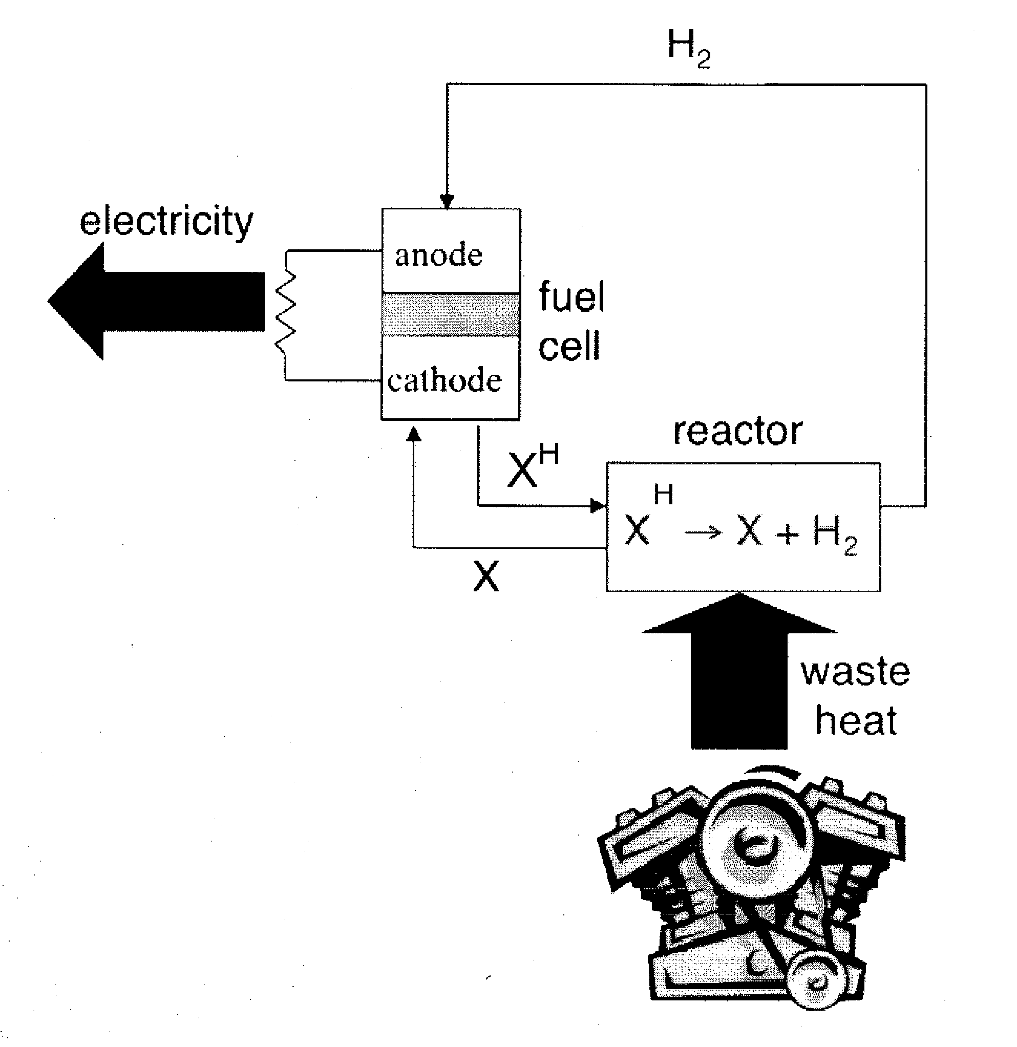
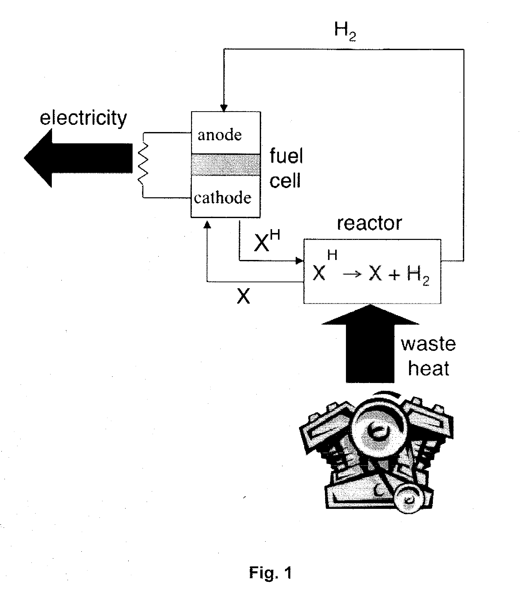
[0067]In a TRFC, a catalyst and a dehydrogenatable liquid (see “XH” in FIG. 1) are placed in a dehydrogenation reactor that is located near a heat source. Such a heat source may be an engine block of a vehicle. Heat energy from the heat source drives an endothermic dehydrogenation reaction of the dehydrogenatable liquid from its saturated form (XH) ...

working examples

[0115]The following chemicals were obtained from Sigma-Aldrich (Oakville, Ontario, Canada) and used as received: Benzyl alcohol (≧99%); α-methylbenzyl alcohol (99+%); decyl alcohol (99%); ethylene glycol (≧99%); 1,2-propanediol (99%); 2,3-butanediol (98%); 1,3-propanediol (98%); 1,3-butanediol (99%); 2,4-pentanediol (98%) (mixture of isomers); 1-methylindole (≧97%); 2,3-benzofuran (99%); 2,3-dihydrobenzofuran (99%); ethylene carbonate (98%); 2-imidazolidone (96%); diethyl succinate (99%); succinic anhydride (99+%); succinimide; bibenzyl (99%); benzylamine (99.5%); N-phenylbenzylamine (99+%); DL-α-methylbenzylamine (99%); ethyl (S)-(−)-lactate (98%); aniline (99%); acetophenone (99%); propiophenone (99%); propylbenzene (98%); hexadecane (99%); nickel ˜60 wt % on kieselghur; ruthenium; 5 wt % on alumina, powder, Degussa type H213; chloroform-d (99.8 atom % D); deuterium oxide (99.9 atom % D); 4,4′-oxybis(benzoic acid) (99%); 3,3′-diaminobenzidine; methanesulfonic acid (99.5%); phospho...

example 1

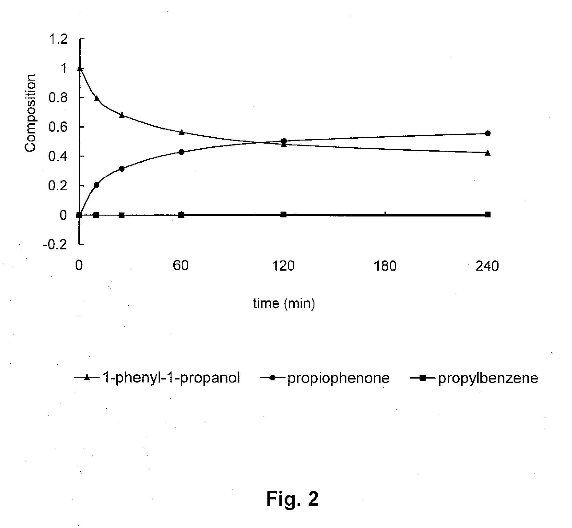
Studies Regarding Rate of Dehydrogenation

[0121]1-Phenyl-1-propanol, a liquid, (5 mL, 4.97 g, 36.5 mmol) was dispensed into a 25 mL pear shaped two-necked reaction flask with 14 / 20 standard taper ground glass joints. To this was added palladium, 5% on silica powder, (reduced, dry Escat™ 1351 available from Strem Chemicals, Inc., Newburyport, Mass., USA) (77.7 mg, 3.9 mg Pd, 9.2 μmol) and a Teflon™ coated magnetic stirring bar. One neck of the flask was fitted with a cold water condenser and the flask was sealed by placing rubber septa in the second neck and at the top of the condenser. A gas bubbler containing silicone oil was connected to the top of the condenser using plastic tubing using a Luer-Lock-to-hose barb adaptor and a 20 gauge 1.5″ long disposable needle which penetrated the septum. A hydrogen cylinder was fitted with a single stage regulator and attached to the reaction flask through its septa using plastic tubing and 6″ needle whose tip was allowed to rest at the bottom ...


PUM

PropertyMeasurementUnit
temperatureaaaaaaaaaa

Abstract

Combinations of catalyst and compound are described that are suitable for use in a thermally regenerative fuel cell. Such combinations offer greater than 99% selectivity and accordingly they cycle through a reversible dehydrogenation process with substantially no loss due to byproduct formation. Combinations of secondary benzylic alcohols and Pd/SiO2 catalysts offer levels of by-products that are undetectable by NMR and GC analysis. With such TRFC, thermal energy can be converted into electric energy in a moving vehicle without the requirement of storage of H2, and its safety issues. Instead, a catalytic amount of H2 is cycled through the system and used to generate electric energy.

Description

FIELD OF THE INVENTION [0001]The field of the invention is energy transformation, and specifically the conversion of heat into electricity by way of a thermally regenerative fuel cell.BACKGROUND OF THE INVENTION[0002]Electrical energy on board a moving vehicle such as a truck, car or ship is expensive because it cannot be obtained from a municipal electrical grid. In a moving vehicle, electrical energy must be stored using batteries or must be generated. Devices that generate electricity (e.g., an alternator) result in decreased fuel efficiency. However, there is waste heat energy available in most moving vehicles. Instead of efficiently converting gasoline or diesel's energy content into motion of the vehicle, an engine block and exhaust system inefficiently converts a large portion of gasoline or diesel's energy content into waste heat. There is a need for a method of converting waste heat into usable electrical energy inside a vehicle to supplement electrical energy available fro...

Claims


Application Information

Patent Timeline
Patent Type & Authority Applications(United States)
IPC IPC(8): H01M8/18C01B3/32
CPCC01B3/22C01B2203/0277Y02E60/528C01B2203/84H01M8/182C01B2203/1217Y02P20/129Y02E60/50
Inventor CARRIER, ANDREW J.DAVIS, BOYD R.JESSOP, PHILIP G.HUYNH, KEITH HAO-KIET
Owner QUEENS UNIV OF KINGSTON
Why Eureka
Try Eureka