Process for the Production of Carbon Graphenes and other Nanomaterials

a carbon graphene and nanomaterial technology, applied in the direction of non-metal conductors, conductors, magnesia, etc., can solve the problems of difficult realization of commercial production of graphenes, limited and significant limitations of known graphene formation processes, etc., to capture and utilize as much of the exothermic energy of reaction

Inactive Publication Date: 2012-03-22
GRAPHENE TECH
View PDF2 Cites 48 Cited by
  • Summary
  • Abstract
  • Description
  • Claims
  • Application Information

AI Technical Summary

Benefits of technology

[0121]The recycling of magnesium is an important part of the invention because of the cost and difficulty of obtaining magnesium of high enough purity for use in the Mg—CO2 reaction, particularly in large scale operations. The crystalline nano MgO produced by the invention has been found to be extremely pure, and this unusually high purity makes recycling the MgO to Mg very practical and cost effective. Given the high cost of magnesium and MgO in the marketplace and the limited availability of pure, non-alloyed magnesium, the ability to recover and recycle highly pure magnesium is an important element and advantage of the invention.
[0122]The preferred process for recycling magnesium in the invention is electrolytic reduction from MgCl2. The chemical and electrolytic steps in the reduction of MgO to Mg by this process are shown in FIG. 17. As illustrated, the MgO reaction product is converted to Mg(OH)2 by treatment with H2O, and the Mg(OH)2 is converted to MgCl2 and H2O by treatment with HCl, with the differential thermal expansion between MgO and carbon opening up cracks in the carbon, allowing the HCl to attach to the carbon. In the electrolysis step, the MgCl2 is separated into magnesium nanoparticles and chlorine gas.
[0124]The invention is designed to preserve, capture and utilize as much of the exothermic energy of reaction as possible. The reaction temperature of approximately 5610° F. (3098° C.) is unusually high and is in a range that can generally be achieved at larger scales only with solar furnaces or via nuclear reaction. In the preferred embodiments, waste heat from the reaction is captured and utilized in post reaction product separation and treatment, including production of electricity for use in the recycling of magnesium. Heat and light energy from the reaction can also be captured and utilized in other applications.
[0126]A thermodynamic analysis of the Mg—CO2 reaction and the recycling of the MgO reaction product is summarized in Table 1 below.TABLE 1Production of Solid Carbon through ReductionOf Gaseous Carbon Dioxide with MagnesiumHeat(MJ / kg)HeatStepReactionThermicityMg(MJ / kg) CAMg (s) + 0.5CO2 (g) → 1MgO (s) + 0.5C (s)Exothermic−16.8−67.507ProductionBMgO (s) + H2O (l) → Mg(OH)2Exothermic−3.37−13.507Mg RecycleCMg(OH)2 (s) + 2HCl (l) → MgCl2 (s) + 2H2O (l)Endothermic5.7422.993Mg RecycleDMgCl2 (s) + Energy → Mg (s) + Cl2 (g)Endothermic22.489.667Mg RecycleTotalEndothermic7.9131.647As this table shows, one cycle of the process requires approximately 8 MJ of energy for each kilogram of magnesium produced and approximately 32 MJ for each kilogram of carbon. Each cycle generates 0.25 kg of carbon by reducing 0.92 kg of CO2, and produces 1.45 kg of chlorine (Cl2). On a molar basis, this can be expressed as:Mg(s)+H2O(l)→Mg(OH)2(s)+0.5C(s)+Cl2,and on a mass basis as:1 kg Mg(s)+0.92 kg CO2+0.75H2O(l)+7.91 MJ→0.25 kg C(s)+1.45 kg Cl2 The reactions were evaluated using a Gibbs free energy analysis that provides a theoretical maximum energy (heat) available for work in each step of the reactions. Steps A and B are exothermic, releasing approximately 20 MJ of heat per kilogram of magnesium while recycling Steps C and D are endothermic, requiring an energy input of approximately 28 MJ to proceed.

Problems solved by technology

To date, however, no process for the production of carbon nanomaterials has been successfully commercialized, despite many serious efforts to do so, particularly with respect to carbon nanotubes.
Therefore, there is justified concern that commercial production of graphenes may also be difficult to realize.
All the known graphene formation processes have significant limitations and disadvantages, including the dependency on relatively scarce highly crystalline graphite as feedstock, high cost, and limited scalability.
Because of these limitations, the known methods may not be capable of providing a dependable supply of low cost graphenes with high volumes of production.
Scientists believe the unusually high levels of CO2 in the atmosphere could cause or are already causing adverse global climate effects and acidification of the oceans.
Since the capture of CO2 from fossil fuel emissions is costly and energy intensive, it would be desirable if at least some of the captured CO2 be put to productive use rather than be treated as a waste product.
However, photosynthesis has the disadvantage of being difficult to replicate in technical or man-made biologic systems.
Partial reduction approaches are currently considered more likely than full reduction of CO2 to carbon to be feasible alternatives to sequestration because full reduction of CO2 is generally believed to be steeply endothermic and, therefore, economically challenging.
However, partial reduction approaches have the disadvantage of producing materials for which the market prices are relatively low.
In sum, previously known CO2 reduction methods are limited practically and economically by one or more factors, including cumbersome mass flow requirements, significant energy requirements, high cost of reactants, difficult or risky materials management, and / or low value of the end products, with the value of the products often being less than the cost of producing them.
However, these processes are relatively expensive and do not always produce the level of purity desired.

Method used


Image

  • Process for the Production of Carbon Graphenes and other Nanomaterials
  • Process for the Production of Carbon Graphenes and other Nanomaterials
  • Process for the Production of Carbon Graphenes and other Nanomaterials

Examples


example 1

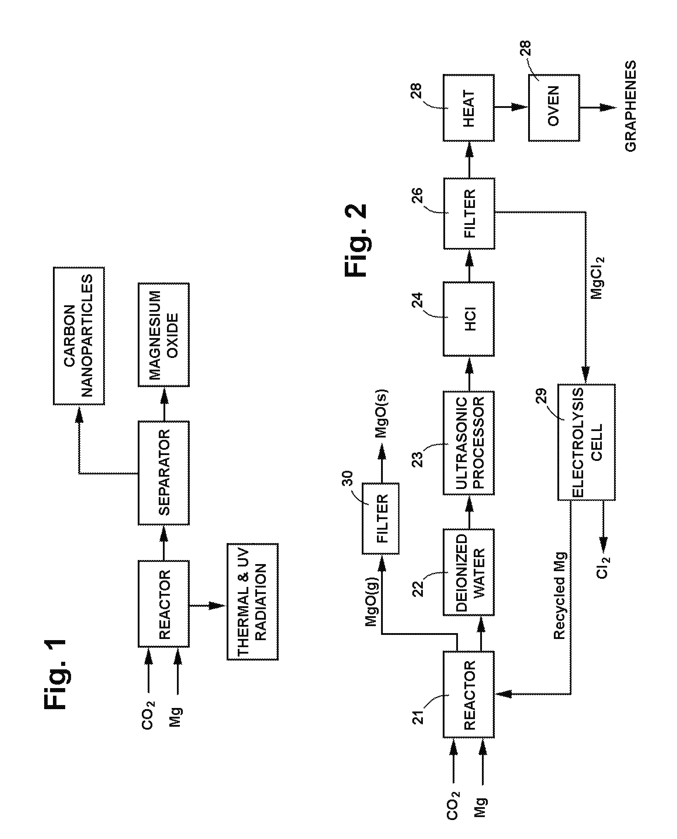
[0127]A reactor was constructed using two blocks of solid CO2, more commonly known as dry ice. A cavity was drilled in one of the dry ice blocks to serve as a reactor vessel, and the other block was used as a cover. Magnesium bar stock was machined into chips which were placed in the cavity and ignited with a propane torch, following which the cover block was immediately placed on top of the first block. The reaction product, a mixture of white and black crusty powder, was collected and sent out for analytical testing. A second sample was prepared in a similar manner and treated with deionized water and hydrochloric acid (HCl) before being sent out for testing.

[0128]The test results showed that the reaction product consisted of nanomaterial and that the nanomaterial consisted of two dominant morphologies as well as some less frequently observed morphologies. The two dominant morphologies were a clear, irregularly shaped, flat particle showing classic evidence of graphitic (carbon) c...

example 2

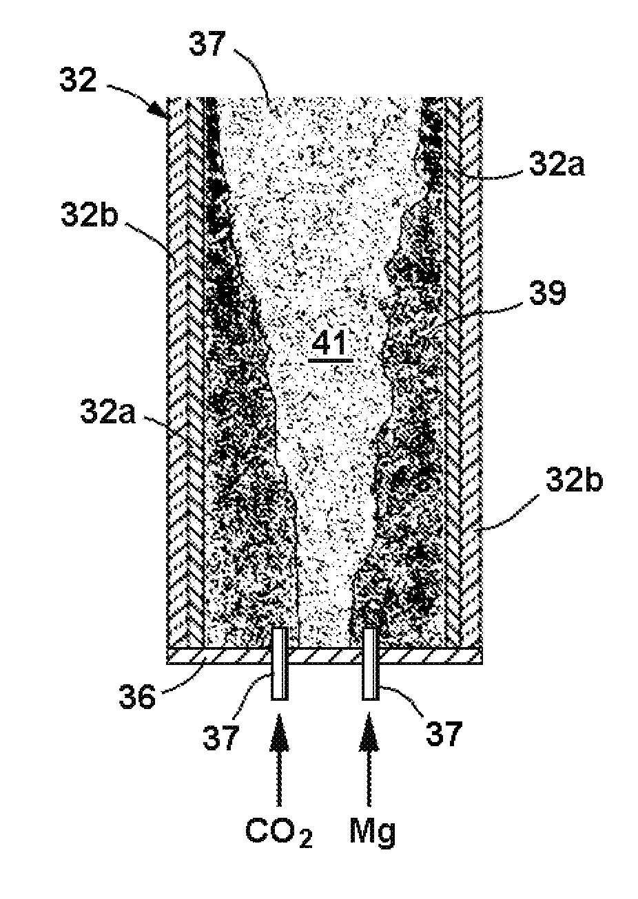
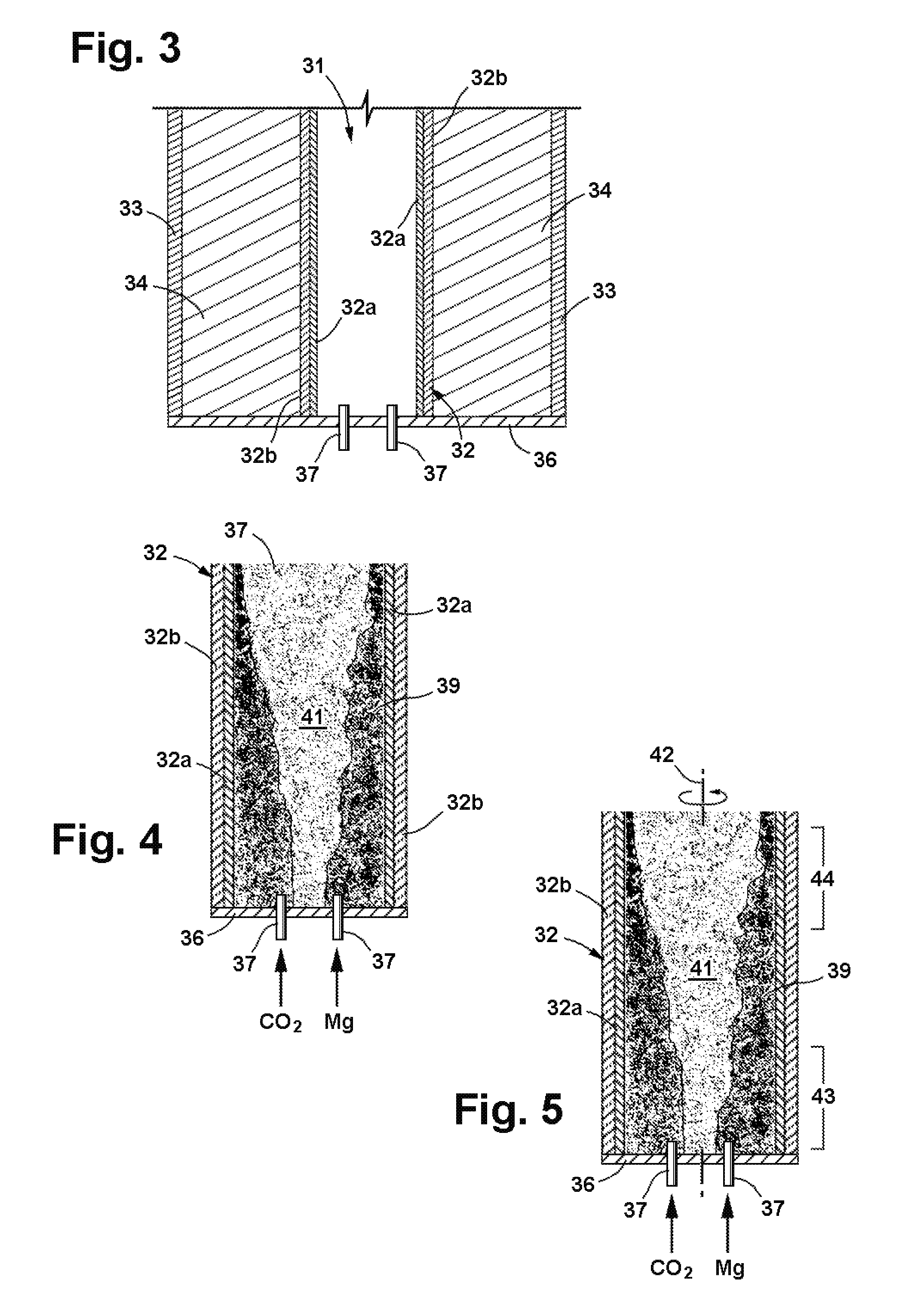
[0132]A reactor was constructed from blocks of solid CO2, or dry ice, which were approximately 12 inches square and 1¾ inches square. A cavity having a diameter of approximately 1⅝″ was drilled into one of the blocks to serve as the reactor chamber. Exhaust pressure release vents having a diameter on the order of ¼ inch were drilled laterally from the outer edges of the block to the cavity. The second block was used as a lid for the reactor.

[0133]Magnesium bar stock believed to have a purity of 99% was machined into several batches of various sized flakes. Approximately 10 grams of magnesium chips of between number 5 and number 10 sieve mesh (2.00-4.00 mm) were placed in the cavity. The flakes were ignited with an oxygen-hydrogen torch and the dry ice lid was immediately place on lower block. The reaction was observed to be extremely vigorous producing a sizable amount of light and resulting in some ejection of white smoky (MgO) material from the edges of the two blocks. The reactio...

example 3

[0143]Magnesium barstock was machined into chips ranging in size between about 2.0 and 4.0 mm (sieve mesh sizes #5-#10). These chips combusted with CO2 in a manner similar to that in Example 2, and two samples were prepared for separation processing.

[0144]As an initial step in the post reaction separation processing, the heterogeneous product samples were ground to a 140 mesh size to reduce agglomeration and provide more uniform samples with greater surface area for fluid treatment. The ground up samples were introduced into a vessel containing deionized water and were processed ultrasonically at 20 kHz and 500 Watts for a defined period of time to further reduce particle size and increase surface area. Thereafter, 12M (moles per liter) HCl was added to dissolve the MgO reaction product as well as any remaining uncombusted Mg. The HCl reacted with MgO and Mg to form MgCl2 in an exothermic reaction. The vessel was allowed to cool, following which the sample was treated with HCl again...


PUM

PropertyMeasurementUnit
temperaturesaaaaaaaaaa
temperatureaaaaaaaaaa
energyaaaaaaaaaa

Abstract

Process for producing nanomaterials such as graphenes, graphene composites, magnesium oxide, magnesium hydroxides and other nanomaterials by high heat vaporization and rapid cooling. In some of the preferred embodiments, the high heat is produced by an oxidation-reduction reaction of carbon dioxide and magnesium as the primary reactants, although additional materials such as reaction catalysts, control agents, or composite materials can be included in the reaction, if desired. The reaction also produces nanomaterials from a variety of other input materials, and by varying the process parameters, the type and morphology of the carbon nanoproducts and other nanoproducts can be controlled. The reaction products include novel nanocrystals of MgO (percilase) and MgAl2O4 (spinels) as well as composites of these nanocrystals with multiple layers of graphene deposited on or intercalated with them.

Description

RELATED APPLICATIONS[0001]This is a continuation-in-Part of Application No. 13 / 090,053, filed Apr. 19, 2011, and is also based upon Provisional Application No. 61 / 385,087, filed Sep. 21, 2010, the priority of which is claimed.BACKGROUND OF THE INVENTION[0002]1. Field of Invention[0003]This invention pertains generally to the production of nanomaterials and, more particularly to the production of carbon graphenes and other nanomaterials.[0004]2. Related Art[0005]Nanomaterials is an emerging new field to which major efforts in research and development are being applied. The characteristics of nanomaterials can differ significantly from those of conventional materials in a number of respects that may be important to applications in many fields, including the medical field, semiconductors, energy storage, advanced composites, electronics, and catalytics. Many nanomaterials can be used in ways that exploit their quantum-mechanical properties.[0006]Recently, significant research and inter...

Claims


Application Information

Patent Timeline
Patent Type & Authority Applications(United States)
IPC IPC(8): C01B31/04B01J19/08C01F5/02H01B1/04B82Y30/00B82Y40/00
CPCB82Y30/00B82Y40/00C01B31/0446C01G9/02C01P2004/64C01G23/04C01G23/07C01P2004/04C01P2004/38C01G9/03C01B32/184
Inventor DICKINSON, ROBERT WAYNEDICKINSON, III, BEN WADE OAKESMYERS, JON K.OUSTERHOUT, OLIVER DOUGLASMUSETTI, LAWRENCE JOSEPH
Owner GRAPHENE TECH
Why Eureka
Try Eureka