Anti-pollution electrocatalysis composite membrane and membrane reactor

a technology of electrocatalysis and composite membrane, which is applied in the direction of membranes, manufacturing tools, electric circuits, etc., can solve the problems of reducing the treatment ability of the membrane, reducing the discharge rate of the membrane, and reducing the treatment efficiency of the membrane, so as to reduce the deposition of the membrane fouling, reduce the discharge rate, and reduce the discharge rate

Active Publication Date: 2012-04-19
TIANJIN POLYTECHNIC UNIV
View PDF5 Cites 16 Cited by
  • Summary
  • Abstract
  • Description
  • Claims
  • Application Information

AI Technical Summary

Benefits of technology

[0006]In one aspect, the present invention relates to an antifouling electrocatalytic composite membrane and a membrane reactor, thus to improve the antifouling property of the known membrane separation material.
[0007]An antifouling electrocatalytic composite membrane, which is characterized in that the electrocatalytic composite membrane consisted of a substrate and a catalytic coating, wherein the substrate is selected from a conductive substrate or a nonconductive substrate coated with a conductive coating, and is a porous support having supporting, conducting and separating functions, the catalytic coating is supported or coated on the surface and in the pores of the conductive substrate or the conductive coating so as to increase the electrocatalytic activity of the substrate; wherein the conductive substrate is carbon membrane, the conductive coating is carbon layer, the nonconductive substrate is ceramic membrane and the catalytic coating is one selected from diamond, graphite, silica, Sb2O3, SnO2, transition metal, rare metal, transition metal oxide and rare metal oxide, or a mixture thereof; the ceramic membrane material is preferably at least one selected from alumina, titanium oxide or zirconia.
[0018](1) the composite membrane may combine the electrocatalytic oxidation technique with membrane separation technique, in which an electronic emitting area may be formed on the membrane surface under the electric field, thus the produced micro-gas / liquid flows may reduce the deposition of the membrane fouling; meanwhile, the strong oxidant generated in the electrocatalysis process, such as hydroxyl free radical, etc., may efficiently decompose the pollutant on the membrane surface, thus strengthening the membrane separation, giving the membrane a self-cleaning function and solving the membrane fouling; in addition, organic matters in the treated liquid may be decomposed well with a low energy exhaust and high treating efficiency, therefore, it can treat industrial wastewater such as oily wastewater, dye wastewater or paper-making wastewater.
[0019](2) the substrate used in the present electrocatalytic composite membrane has good and stable corrosion resistance, which may prevent anode dissolving; the substrate and catalytic coating were efficiently integrated into one by surface modification technique to ensure the structural stability of the composite membrane; the coated catalytic coating is used to improve the electrocatalytic property of the substrate membrane, thus further increase the degradation efficiency of the composite membrane electrode to the organic matter in the wastewater. Membrane separation is still major during the wastewater treating, while the membrane electrode plays a positive role in oxidizing the pollutants attached on the surface and in the pores of the membrane so as to keep a high membrane flux, prolong the life time of the membrane and solve the membrane fouling in the actual application. Therefore, the present composite membrane is very suitable to the industrial application for its high separation efficiency, strong antifouling property and low energy exhaustion, and no secondary pollution exists.

Problems solved by technology

During the wastewater treatment with membrane, however, fouling deposited on the membrane surface and in the pores may result in an increased trans-membrane pressure, a reduced membrane flux (separation efficiency) and a quick reduction of membrane treatment ability.
Thus the life time of the membrane is shortened and the reliability and economy are badly affected during the membrane separation.
Obviously, membrane fouling has become a bottleneck to limit wide application of membrane separation technique.
But this technique has disadvantages that solar energy was used with a low efficiency and the suspended catalyst is difficult to recover.
However, there are still the problems of second fouling and additive recovering for the addition of coagulant.
The membrane bioreactor has a compact structure and can be easily controlled automatically, but there are still problems that the microorganism is difficult to control and bio-pollution is serious.
However, anode used in this device is metal material such as stainless steel and copper, which makes anode easily dissolved and results in secondary fouling and poor operation stability.
In addition, the composite of polymeric conductive layer and metal substrate is unstable too.

Method used


Image

  • Anti-pollution electrocatalysis composite membrane and membrane reactor
  • Anti-pollution electrocatalysis composite membrane and membrane reactor
  • Anti-pollution electrocatalysis composite membrane and membrane reactor

Examples


example 1

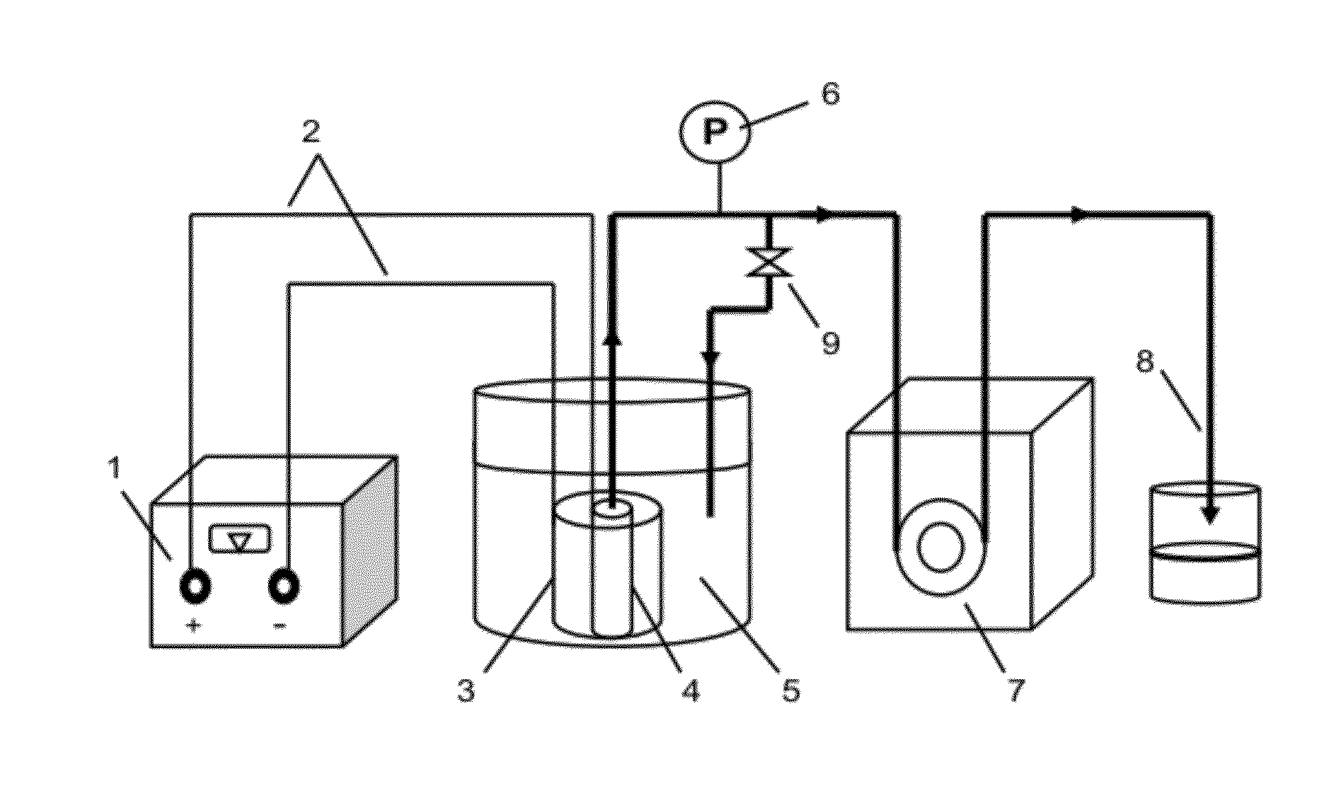
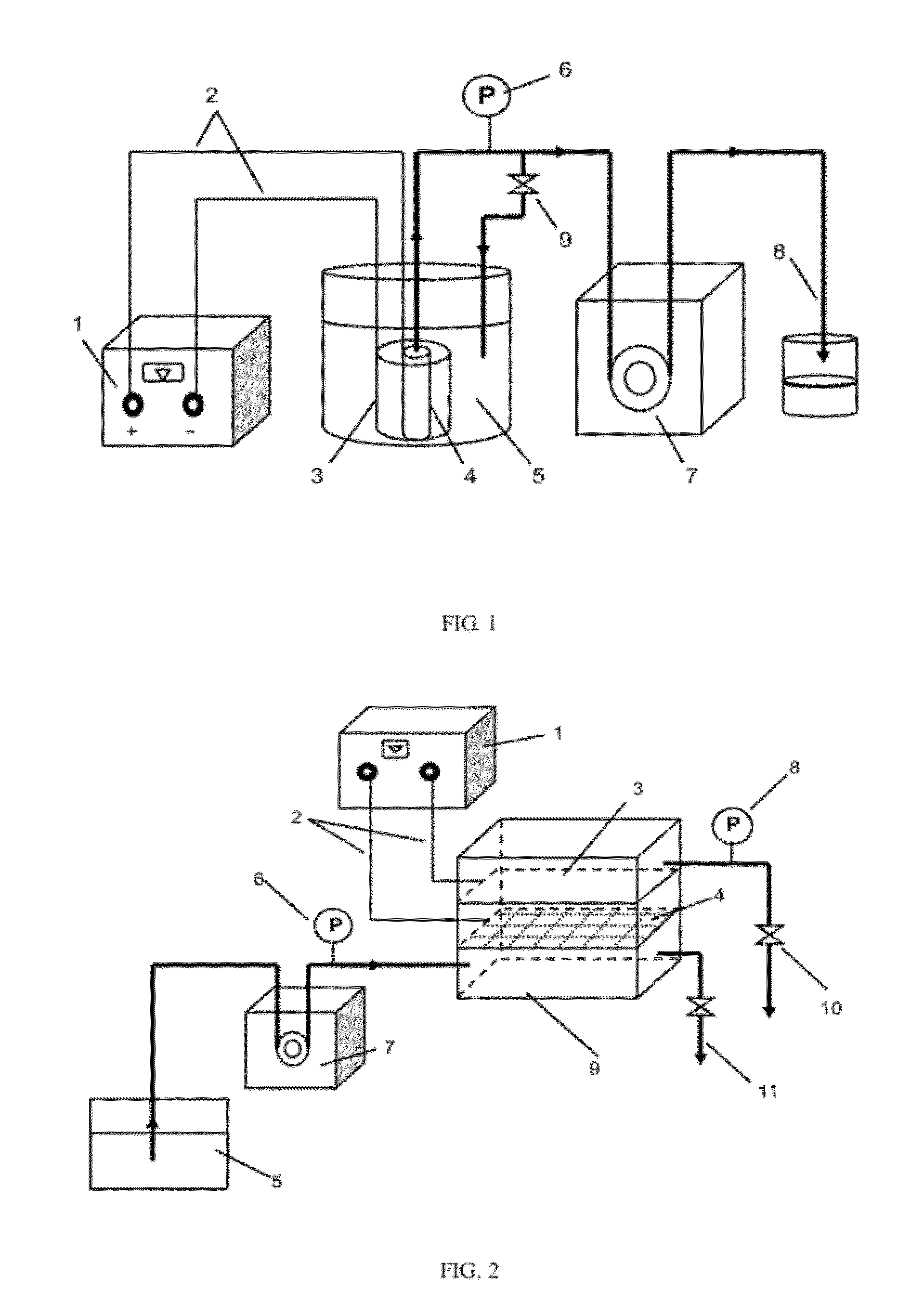
[0034]As for the electrocatalytic membrane reactor comprised of the electrocatalytic composite membrane according to the present invention, when the electrocatalytic composite membrane was a tubular membrane, the electrocatalytic membrane reactor formed therefrom was shown in FIG. 1. The electrocatalytic composite membrane 3 was putted into the feed liquid of feed liquid bath 5, wherein the electrocatalytic composite membrane 3 had a closed end and the other end thereof was connected to peristaltic pump 7 by pipelines. Peristaltic pump 7 was used to provide negative pressure continuously so that feed liquid permeates through the electrocatalytic composite membrane 3 from the outside in and flows out via permeate outlet valve 8. A branch regulating valve 9 was arranged on the line of pipes via which permeate flows through. Meanwhile, the electrocatalytic composite membrane 3 as anode and an auxiliary electrode 4 as cathode were connected to an adjustable direct current regulated powe...

example 2

[0036]The electrocatalytic composite membrane in this example consisted of tubular carbon membrane substrate and metal-silica coating.

Substrate: carbon membrane (average pore size 0.6 μm; tubular size Φ8.8 mm×1.4 mm, which meant outer diameter and thickness of the tube, and tubular sizes in the following examples had the same meaning.)

Catalytic coating: Pt / SiO2

Preparation: sol-gel approach

[0037]The above electrocatalytic composite membrane was prepared as follows:[0038](1) substrate pretreatment: a carbon membrane was ultrasonic cleaned for 30 min in ethanol solution, then pretreated for 10 h by hydrogen peroxide solution with a mass percent 20%, and then washed with water and dried at 120° C. in an oven;[0039](2) preparation of Pt / SiO2 sol: ethyl orthosilicate, absolute ethyl alcohol, distilled water and acetylacetone (hydrolysis inhibitor) were mixed uniformly in a molar ratio 1:20:1.5:0.8, then hydrochloric acid was added therein to adjust pH around 2 and the mixture was strongl...

example 3

[0045]The electrocatalytic composite membrane in this example consisted of tubular carbon membrane substrate and metal oxide coating.

Substrate: carbon membrane (average pore size 0.4 μm; tubular size Φ8.8 mm×1.4 mm)

Catalytic coating: TiO2

Preparation: sol-gel approach

[0046]The above electrocatalytic composite membrane was prepared as follows:[0047](1) substrate pretreatment: the substrate pretreatment was the same as that in example 2;[0048](2) preparation of TiO2 sol: tetrabutyl titanate, absolute ethyl alcohol, distilled water, glacial acetic acid and acetylacetone were formulated in a molar ratio 1:18:2:0.2:0.5, then the mixture was strongly stirred for 2 h and was aged for 24 h at room temperature for next step;[0049](3) preparation of composite carbon membrane: the carbon membrane substrate was immersed in TiO2 sol, then stably pulled from the sol at a speed of 3 mm / s after it was settled for 30 s and dried at room temperature;[0050](4) sintering: the coated substrate obtained ...


PUM

PropertyMeasurementUnit
pore sizeaaaaaaaaaa
distanceaaaaaaaaaa
currentaaaaaaaaaa

Abstract

The present invention relates an antifouling electrocatalytic composite membrane and a membrane reactor. The electrocatalytic composite membrane (3) consists of a substrate and a catalytic coating, wherein the substrate is selected from a conductive substrate or a nonconductive substrate coated with a conductive coating, and the substrate is a porous support having supporting, conducting and separating functions. The catalytic coating is supported or coated on the surface and in the pores of the conductive substrate or the conductive coating so as to increase the electrocatalytic activity of the substrate. The membrane reactor provides a trans-membrane pressure as the membrane separation power generated by a pump (7) and dead-end filtration or cross-flow filtration is applied, then the feed liquid permeates through the membrane from one side to the other to achieve the separation of the liquid; meanwhile, an electrocatalytic composite membrane (3) as anode and an auxiliary electrode (4) as cathode are connected to a power supply (1) separately by conducting wires (2) so that an electrolysis apparatus is formed. The electrocatalytic composite membrane (3) has a self-cleaning function and achieves the pollution-free operation during the membrane separation.

Description

TECHNICAL FIELD[0001]The present invention relates to membrane material technique, in particular to an antifouling electrocatalytic composite membrane and a membrane reactor.BACKGROUND[0002]As a high efficiency and environmental friendly separation technique, the membrane separation technology becomes a key technique to solve a series of fundamental problems such as energy, resource and environment problems. During the wastewater treatment with membrane, however, fouling deposited on the membrane surface and in the pores may result in an increased trans-membrane pressure, a reduced membrane flux (separation efficiency) and a quick reduction of membrane treatment ability. Thus the life time of the membrane is shortened and the reliability and economy are badly affected during the membrane separation. Obviously, membrane fouling has become a bottleneck to limit wide application of membrane separation technique. Therefore, it has become key points to control membrane fouling and to inc...

Claims


Application Information

Patent Timeline
Patent Type & Authority Applications(United States)
IPC IPC(8): C25B13/04C25B15/02
CPCB01D67/0048B01J2219/00247B01D71/021B01D71/022B01D71/024B01D71/027B01D2313/345B01D2315/08B01D2315/10B01D2325/10C02F1/444C02F1/4672C02F1/469B01J19/2475B01D69/145Y02W10/37
Inventor LI, JIANXINWANG, TONGHUAMA, JUNLIANG, XIAOPINGYANG, YANGWANG, HONG
Owner TIANJIN POLYTECHNIC UNIV
Why Eureka
Try Eureka