Method, system and equipment for gasification-liquefaction disposal of municipal solid waste

a gasification-liquefaction and municipal solid waste technology, applied in the direction of combustible gas production, combustible gas purification/modification, energy input, etc., can solve the problem of no excessive oxide rate in syngas that can effectively inhibit the production of dioxin, and achieve the effect of avoiding dioxin contamination, avoiding severe harm to the environment and zero emissions

Inactive Publication Date: 2013-01-10
QUZHOU CITY GUANGYUAN DOMESTIC GARBAGE LIQUEFY TECH INST
View PDF0 Cites 22 Cited by
  • Summary
  • Abstract
  • Description
  • Claims
  • Application Information

AI Technical Summary

Benefits of technology

[0017]The beneficial effect of the present invention is the gasification-liquefaction disposal for MSW can realize zero emissions and avoid dioxin contamination. No pollutant is released throughout the disposal process and the produced methanol products can be used as chemical raw materials or industrial fuel. The economic benefits obtained are much higher than waste incineration power. Waste incineration produces large amount of carbon dioxide gas and other pollutant emissions, harming the environment severely. The technology of the present invention does not emit smoke and does not pollute the environment. Waste incineration will inevitably produce highly toxic dioxin that is difficult to eliminate and is harmful to human health when the flue gas is released to the atmosphere. The present invention can inhibit the formation of dioxin. Even if an extremely small amount of dioxin appears, it is also easy to clear by purification equipment at a terminal end. Compared with waste landfill disposal, the technology of the present invention does not release any pollutants and greenhouse gases. Waste landfill disposal transfers the pollution to underground, emits large quantities of greenhouse gases, contaminates soil and groundwater, endangering the health of the human body and also affecting the next generations of human being. The present invention utilizes waste as a resource to produce clean energy, reduce energy pressure and meanwhile generate economic benefits. After the disposal is commercialized, government will not bear any cost. The waste landfill is not only a waste of resources, but also a bottomless pit for its cost, giving a large financial pressure on government. The land occupied by the technology of the present invention is much less than waste landfill. The present invention is suitable for harmless resource disposal of municipal solid waste, rural solid waste, medical waste, industrial high polymer waste, agricultural and forestry wastes, composting remainder and waste in waste sorting sites.

Problems solved by technology

The rate of excessive oxide in syngas is none that can effectively inhibit the production of dioxin.

Method used


Image

  • Method, system and equipment for gasification-liquefaction disposal of municipal solid waste
  • Method, system and equipment for gasification-liquefaction disposal of municipal solid waste
  • Method, system and equipment for gasification-liquefaction disposal of municipal solid waste

Examples


example 1

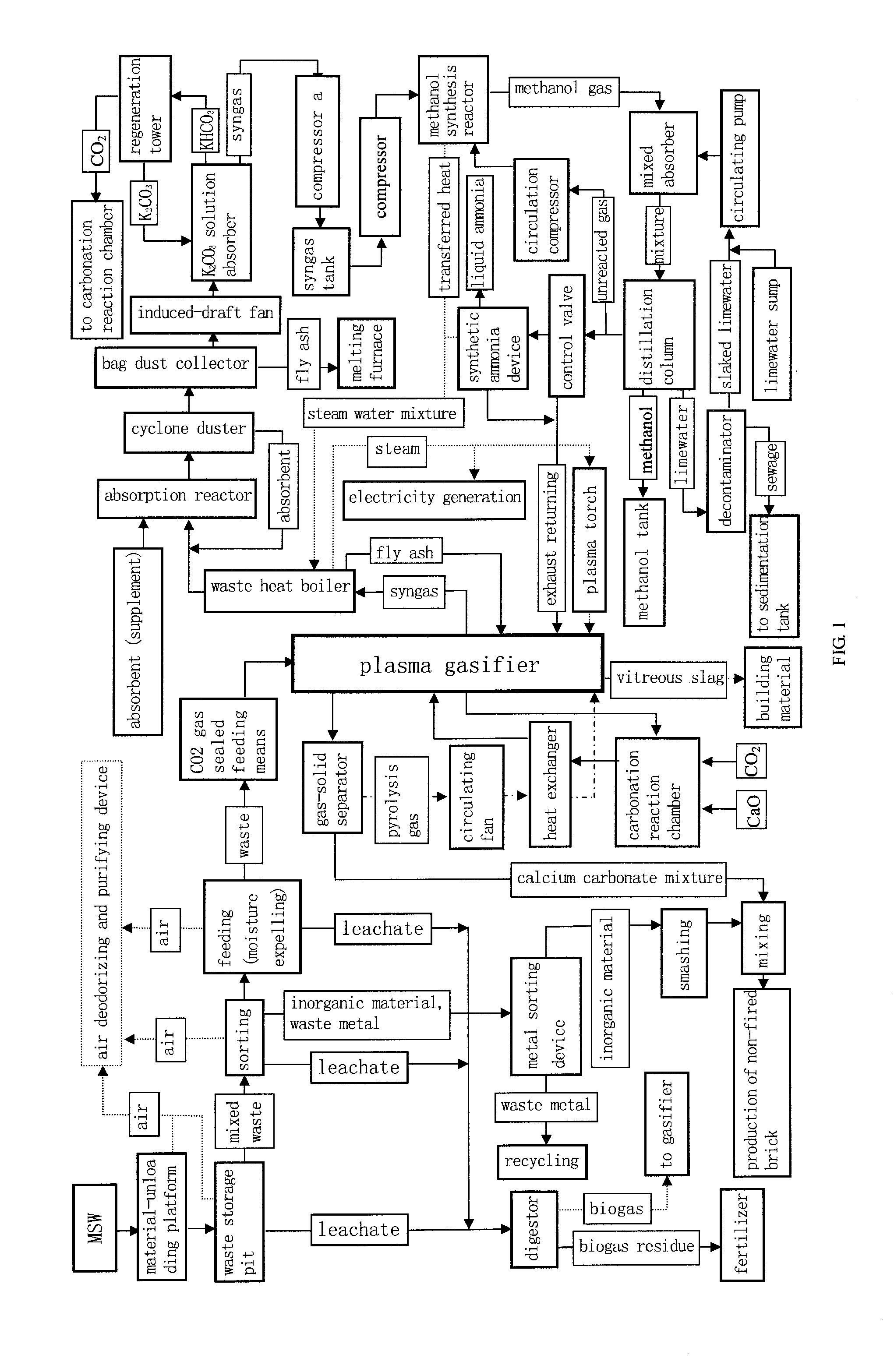
[0030]In the embodiment shown in FIG. 1, MSW or organic waste in the waste storage pit was dehydrated to some extent by the way of fermentation, and then through separation organic matter waste separated was fed into a spiral moisture expelling and feeding means. In the process of conveying through the screw feeder, some amount of water was removed further by extrusion. Then the waste material was fed into a plasma gasifier through a CO2 gas sealed device. The MSW, after dried in drying section of plasma gasifier and pyrolyzed in pyrolysis section of plasma gasifier, became MSW carbon and entered the gasification section for gasification reaction with the decomposer of the water steam injected into the gasification section from a plasma torch, and completed gasification and generates hydrogen-rich syngas in which CO and H2 are the main components. The operating temperature of drying section was at between 120 to 300° C.; the operating temperature of pyrolysis section is between 300 ...

example 2

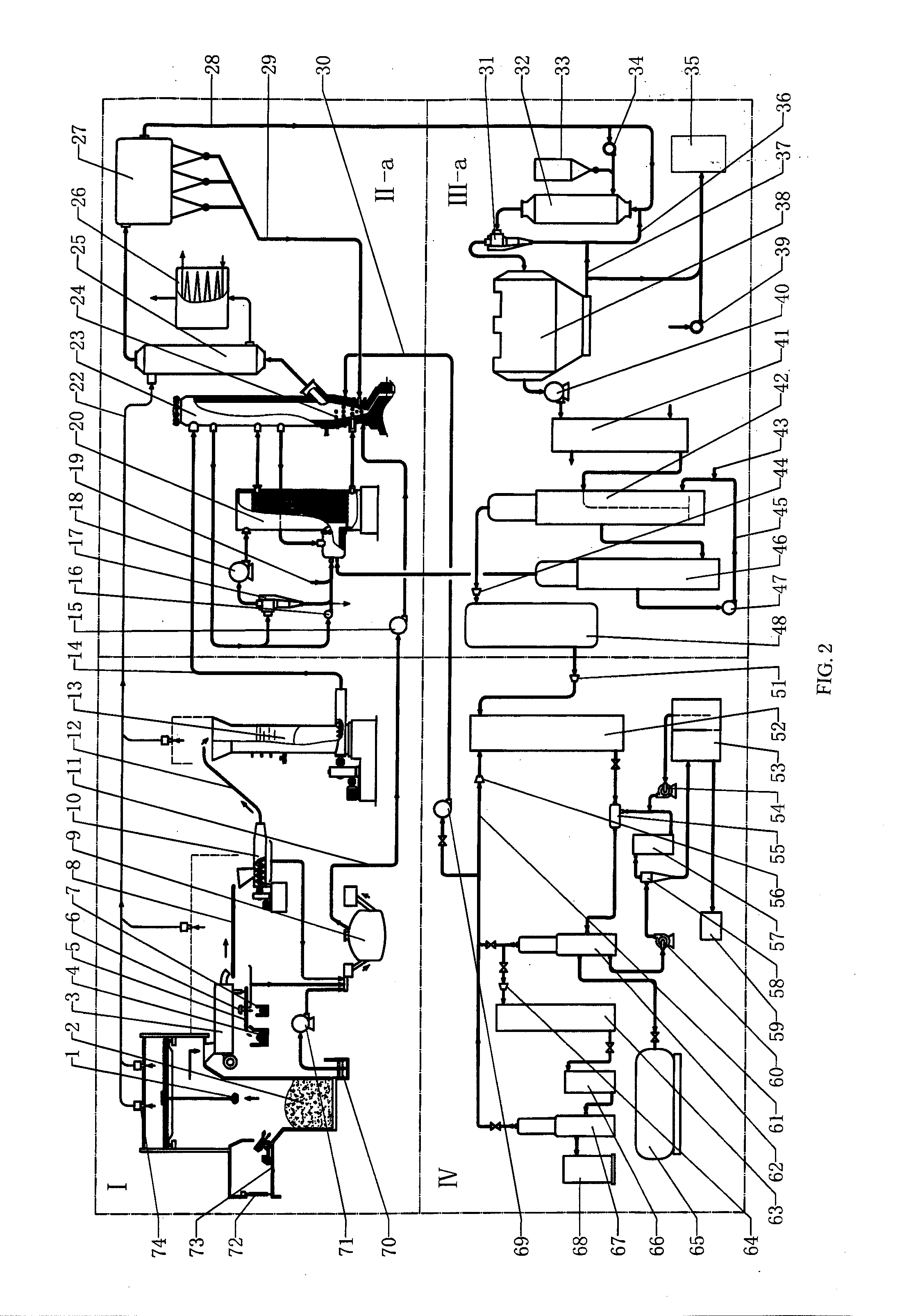
[0031]As shown in the system diagram of FIG. 2 and detailed drawings in FIGS. 4, 5, 6, 7 of the present invention, a MSW gasification-liquefaction disposal system comprises: a MSW pretreating zone (zone I in FIG. 2), a plasma gasification zone (zone II-a of FIG. 2), a syngas purification zone (zone III-1 of FIG. 2) and a zone of methanol synthesis and a terminal purification zone (zone IV of FIG. 2). The system comprises a material-unloading platform (73), a waste storage pit (2), a crane grab (1), a sorting machine (3), spiral moisture expelling and feeding means (10), CO2 gas sealed feeding means (13), a plasma gasifier (23), a plasma torch (24), a gas-solid separator (17), a circulating fan (18), a carbonation reaction chamber (2007), a heat exchanger (20), a waste heat boiler (27), an absorption reactor (32), a cyclone duster (31), a bag dust collector (38), an induced-draft fan (40), a CO shift reactor (41), a CO2 absorber (42), a regeneration repercussion tower (46), a compres...

example 3

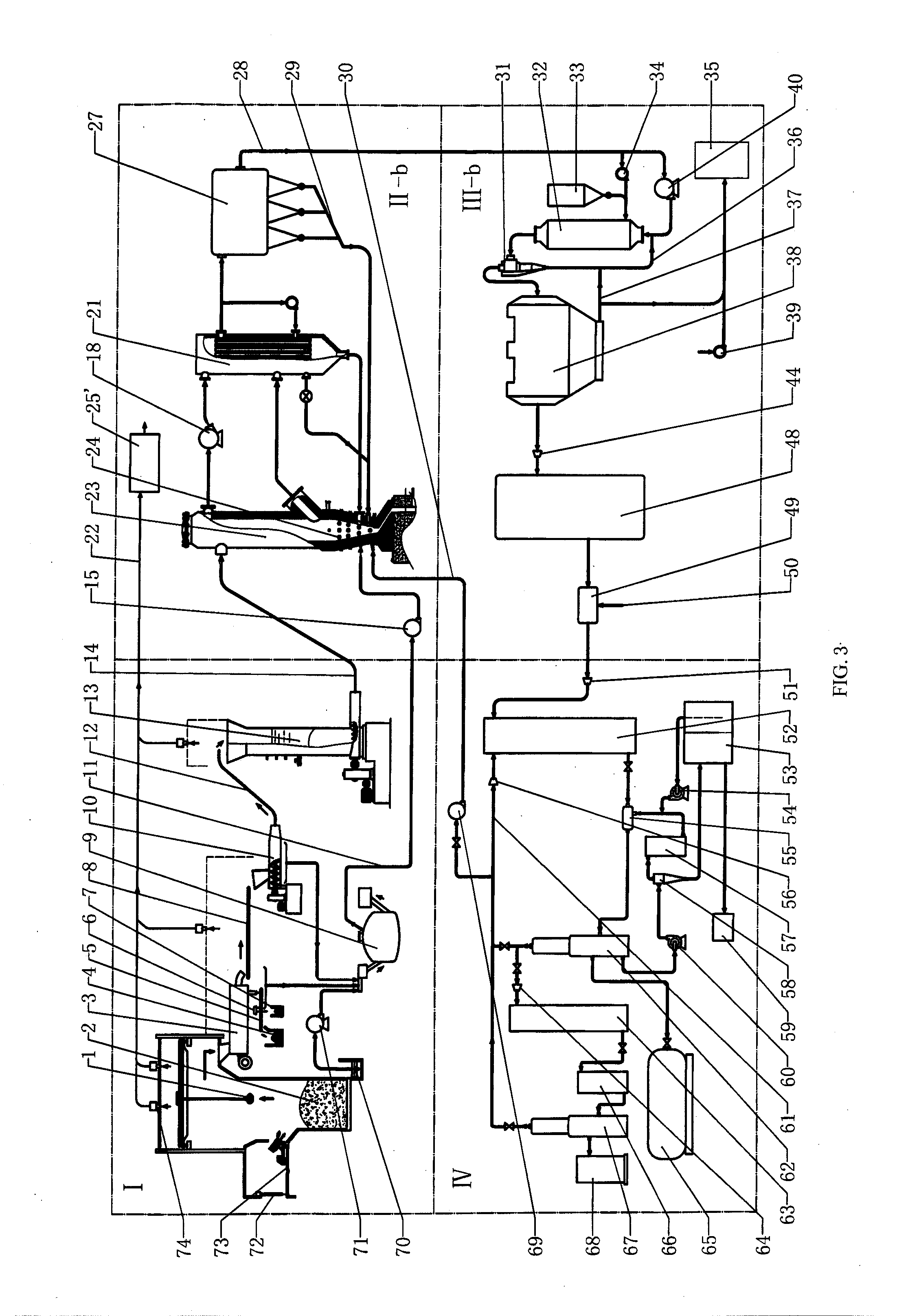
[0032]As shown in the system diagram of FIG. 3 and detailed drawings in FIGS. 4, 7, 8, 9 of the present invention, a MSW gasification-liquefaction disposal system comprises: MSW pretreating zone (zone I in FIG. 3), a plasma gasification zone (zone II-b of FIG. 3), syngas purification zone (zone III-b of FIG. 3), a zone of methanol synthesis and terminal purification (zone IV of FIG. 3). The system comprises a material-unloading platform (73), a crane grab (1), a waste storage pit (2), a sorting machine (3), a digester (9), spiral moisture expelling and feeding means (10), CO2 gas sealed feeding means (13), a plasma gasifier (23), a plasma torch (24), a circulating fan (18), a heat exchanger b (21), a waste heat boiler (27), an induced-draft fan (40), an absorption reactor (32), a cyclone duster (31), a bag dust collector (38), a compressor a (44), a syngas tank (48), a hydrogenation mixer (49), a compressor i (51), a methanol synthesis reactor (52), a mixed absorber (55), a decontam...


PUM

PropertyMeasurementUnit
operating temperatureaaaaaaaaaa

Abstract

A gasification-liquefaction disposal method, system and equipment for MSW are disclosed. The method involves the MSW pretreatment of dehydrating and separating, thus reducing water and inorganic substance content of the waste. Then, the MSW is introduced into a plasma gasifier (23) by a carbon dioxide air-sealed feeding device (13) and gasified therein to obtain hydrogen-rich syngas. The hydrogen-rich syngas is then cooled, deacidified, dedusted and separated to obtain carbon dioxide. Then, the hydrogen-rich syngas is catalyzed to produce methanol product in a methanol synthesis reactor (52). The separated carbon dioxide is sent back to a carbonation reaction chamber (2007) of a gasification system to perform carbonation reaction with calcium oxide, thereby releasing heat to provide assistant heat energy for gasification and avoiding greenhouse gas from being discharged into environment. Exhaust gas is returned to the plasma gasifier (23) for remelting treatment, thus forming a closed-loop circulation production system and realizing the disposal of the MSW with zero discharge and no pollution, thereby avoiding dioxin pollution and converting the MSW to chemical raw materials and fuel needed by mankind The method, system and equipment are suitable for harmless and recycling disposal of MSW, industrial high polymer waste, composting waste and waste in waste sorting sites.

Description

FIELD OF THE INVENTION[0001]The present invention relates to the technology of solid waste disposal, and more specially relates to a method and equipment for the disposal of municipal solid waste (hereinafter referred to as MSW) or organic waste.DESCRIPTION OF THE PRIOR ART[0002]With growing economic development and constant expansion of city scale, municipal solid waste and organic waste are rapidly increasing like a flood. Now garbage besiege appear in many cities of many countries, affecting sustainable economic development and restricting urban development. MSW and organic waste contain many harmful ingredients that, if not handled properly, will pollute environment and threaten human health. Presently, MSW disposal technology mainly includes garbage sorting and comprehensive utilization, sanitary landfill, composting (biochemical) and incineration. Among these technologies, garbage sorting has not been implemented in many countries because it requires public participation. Even...

Claims


Application Information

Patent Timeline
Patent Type & Authority Applications(United States)
IPC IPC(8): C07C29/48B01J19/00
CPCY02E50/32C10K1/122C10J3/30C10J2300/0946C10J2300/1238C10J2300/1665C10J2200/15C10J3/18C10J3/24C10K1/005C10K1/024C10J2300/0906C10J2300/0909C10J2300/0996C05F17/0027C05F9/00B09B3/0083C10J3/20C07C29/1518Y02E50/343C10K1/20C10K1/026C10J2300/1807C10J2300/1668C10J2300/1634C07C31/04Y02W30/20Y02P20/145Y02P20/129C05F17/50Y02A40/20Y02E50/30Y02W30/40B09B3/40
Inventor ZHOU, KAIGEN
Owner QUZHOU CITY GUANGYUAN DOMESTIC GARBAGE LIQUEFY TECH INST
Why Eureka
Try Eureka