Composite electrodes for lithium ion battery and method of making

a lithium ion battery and composite electrode technology, applied in the direction of sustainable manufacturing/processing, cell components, secondary cell details, etc., can solve the problems of poor electronic conductivity, limited lithium ion from liquid and energy storage particles, limiting the performance and the lifetime of traditional lithium ion cells, etc., to reduce internal porosity

Inactive Publication Date: 2013-05-02
QUANTUMSCAPE CORP
View PDF2 Cites 27 Cited by
  • Summary
  • Abstract
  • Description
  • Claims
  • Application Information

AI Technical Summary

Benefits of technology

[0029]calendaring the cured composite to reduce internal porosity; and,

Problems solved by technology

Carbon-coating of the powder particles is necessary to achieve good performances because of the rather poor electronic conductivity of NASICON structures.
Thus the transport of lithium ion from the liquid and the energy storage particles is limited by the surrounding insulative binder film; this leads to local solid electrolyte interface (SEI) layer formation around the particles because of the side reaction taking place between the liquid electrolyte and organic binder film.
The continuous adverse change in the properties of this SEI layers limit the performance and the lifetime of the traditional lithium ion cells.
The energy density of the cell is low because of thick electrodes, also the fundamental low cycle life affecting the traditional cell due to SEI layer has not been addressed by this approach.
Importantly, the LiCoO2 particle coating was done with Pulse Laser Deposition (PLD), a process that is relatively unsuitable for routine manufacturing.
And all the solid state cells were made by pressing the stack of powder of various components into small area cylindrical disk, a cell fabrication technique that is not readily scalable.
The mechanical contact between the particles that dependent on pressing pressure provides less than ideal electrical contact between various particles.
The latter combined with too thick solid state electrolyte layer in the cell leads to undesirable overall cell impedance that limits the extractable capacity.

Method used


Image

  • Composite electrodes for lithium ion battery and method of making
  • Composite electrodes for lithium ion battery and method of making
  • Composite electrodes for lithium ion battery and method of making

Examples


example 1

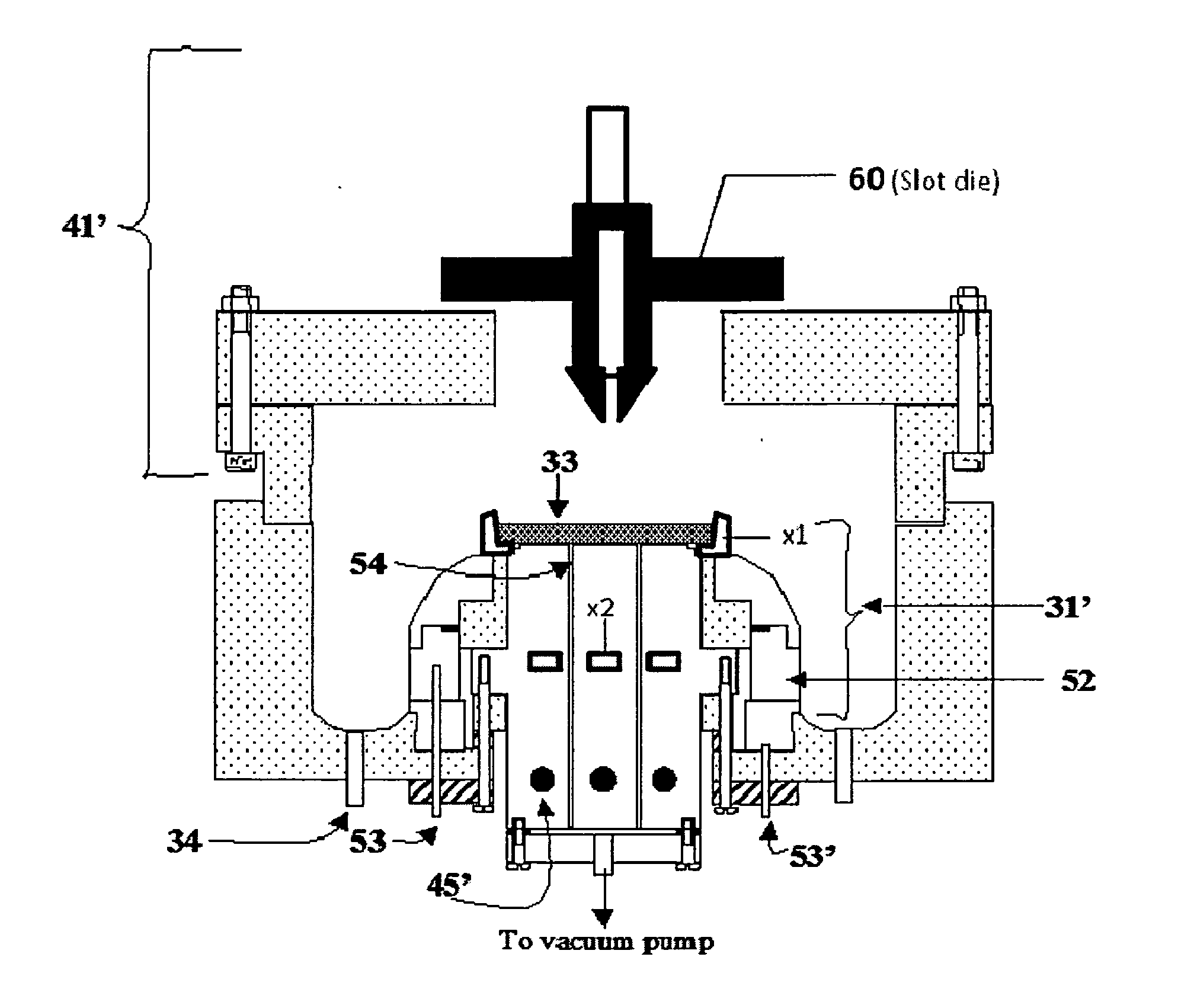
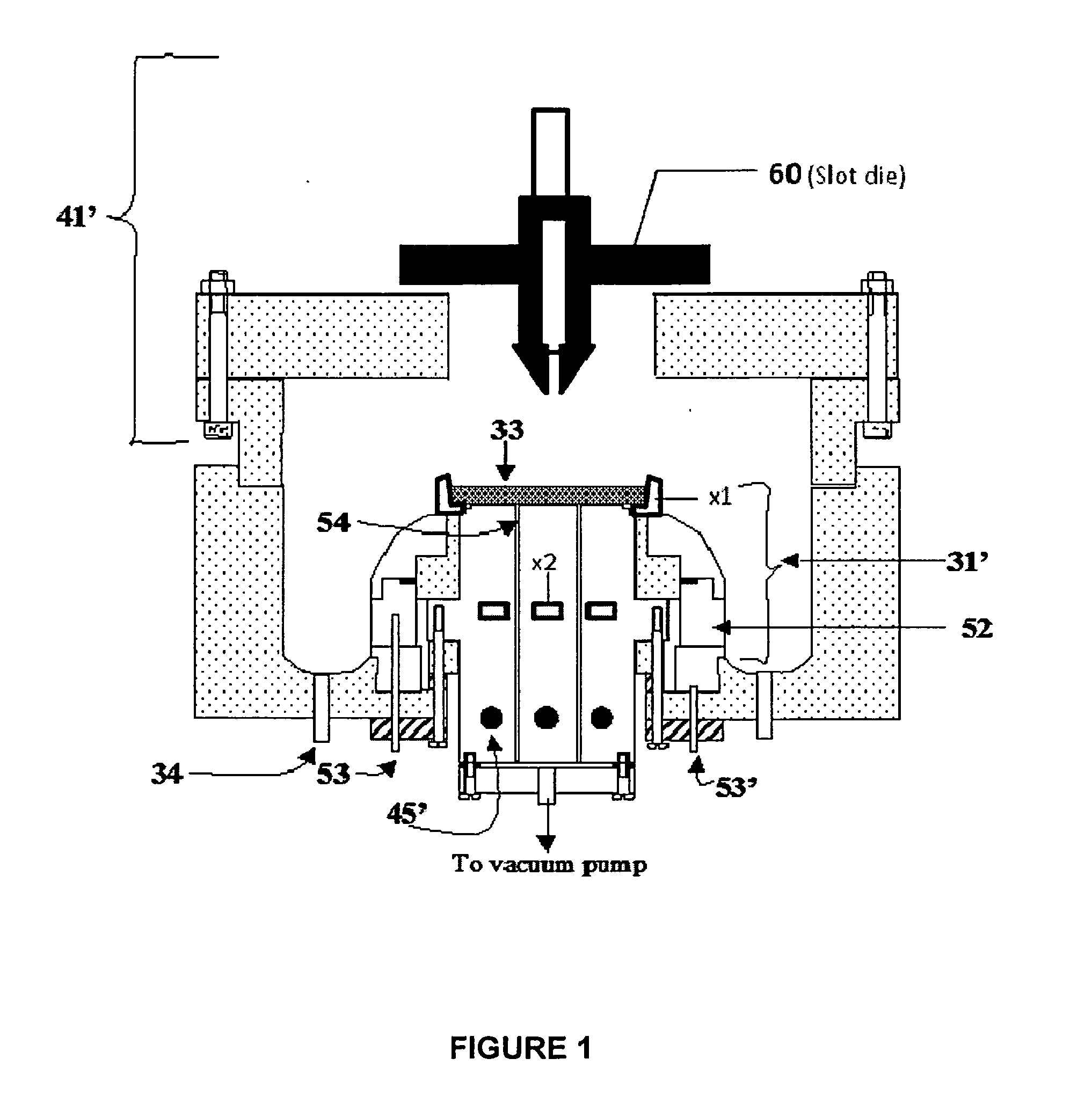
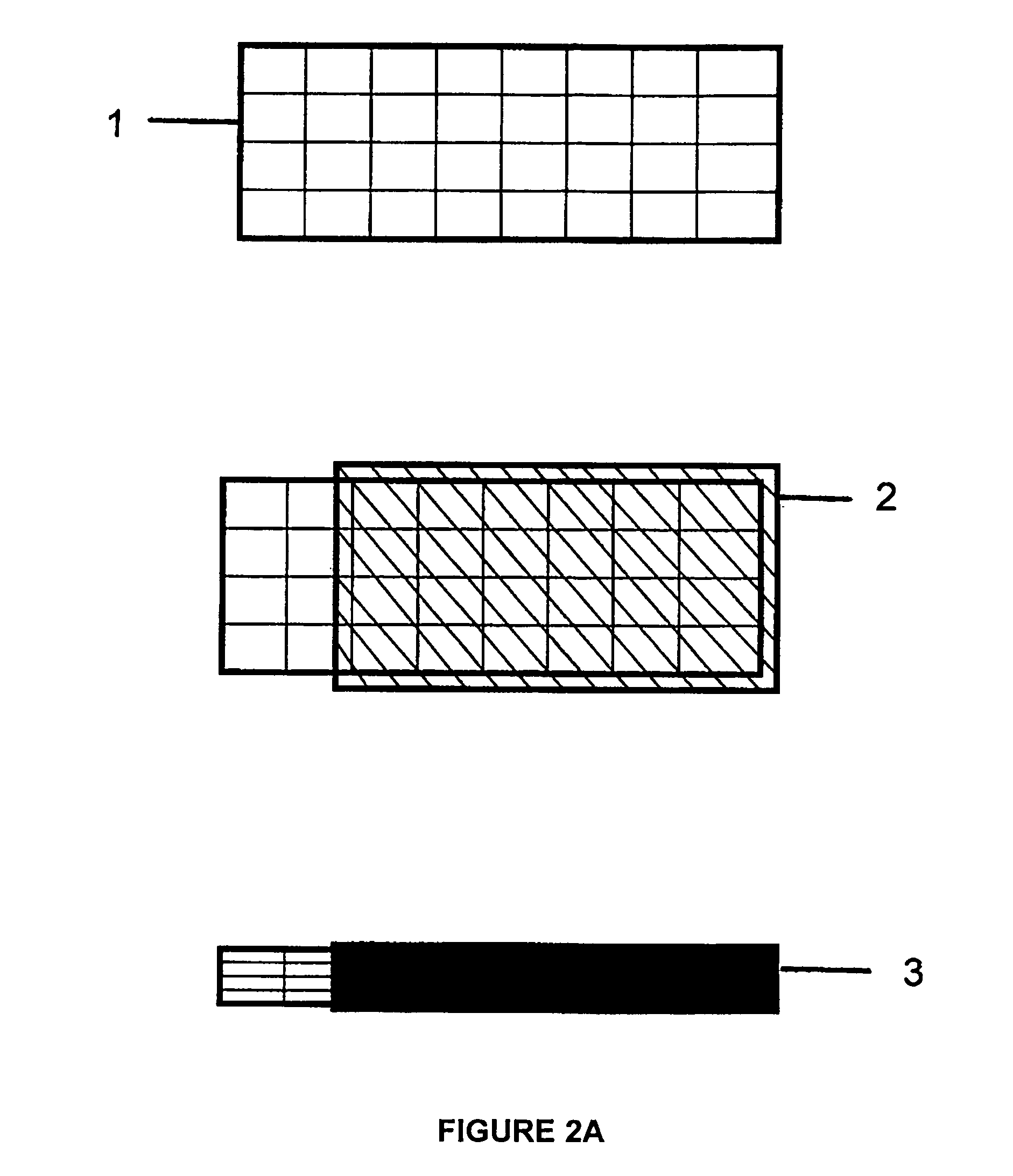
[0076]To form a LiCoO2:Al composite cathode, 9.0 g cobalt nitrate, 3 g urea, 1.0 g Al(NO3)3, and 3.0 g Li(NO3) were dissolved in 50 ml of de-ionized water and heated until the CoAlLi[complex]O nuclei is formed and the hot solution is 20 ml. 5 ml of 1M citric acid was then added. This was followed by 1 ml of 40 wt. % lithium polysilicate in deionized water. The mixture was then sonicated to form a gel. Then, 0.3 g of Li1.3Al0.3Ti1.7(PO4)3 and 0.3 g of TiOx nanoparticles were added for improved ionic conductivity and electronic conductivity respectively. The gel was then resonicated to homogenize the gel. The GELSPEED process was then used to populate a 3″×3″ Ni foam substrate 1 heated at 150° C. The coated foam 2 was cured at 250° C. for about 5 minutes. Coating and curing were repeated 2 more times. Additional curing was done in a box furnace at 300° C. for 10 minutes. This was followed by calendaring under a 100 ton press to compact and densify the self supporting composite LiCoO2:...

example 2

[0077]To form a CuS composite cathode, 5 g copper nitrate, 5 g thiourea, and 4 ml hydrazine monohydrate were dissolved in 50 ml de-ionized water and heated until the Cu[complex]S nuclei was formed and the hot solution was 20 ml. 4 ml of 1M acetic acid was then added. This was followed by 1 ml of 40 wt. % lithium polysilicate in deionized water. The mixture was then sonicated to form a gel. Then, 0.3 g Li1.3Al0.3Ti1.7(PO4)3 and 0.3 g TiOx nanoparticles were added for improved ionic conductivity and electronic conductivity respectively. The gel was then resonicated to homogenize the gel. The GELSPEED process was then used to populate a 3″×3″ Ni foam substrate heated at 150° C. The coated foam was cured at 200° C. for about 5 minutes. Coating and curing were repeated 2 more times. Additional curing was done in the tube furnace at 300° C. for 10 minutes in sulfur ambient. This was followed by calendaring under a 100 ton press to compact and densify the self supporting composite CuS cath...

example 3

[0078]To prepare a SnO composite anode, 5 g tin ethoxide, 0.4 g urea, 0.5 g Al(NO3)3, and 0.3 g Li(NO3) were dissolved in 50 ml of de-ionized water and heated until the SnAlLi[complex]O nuclei was formed and the hot solution is 20 ml. 4 ml of 1M acetic acid was then added. This was followed by 1 ml of 40 wt. % lithium polysilicate in deionized water. The mixture was then sonicated to form a gel. Then, 0.3 g Li1.3Al0.3Ti1.7(PO4)3 and 0.3 g TiOx nanoparticles were added for improved ionic conductivity and electronic conductivity respectively. The gel was then resonicated to homogenize the gel. The GELSPEED process was then used to populate a 3″×3″ Ni foam substrate heated at 150° C. The coated foam was cured at 250° C. for about 5 minutes. Coating and curing were repeated 2 more times. Additional curing was done in a box furnace at 300° C. for 10 minutes. This was followed by calendaring under a 100 ton press to compact and densify the self supporting composite SnO anode. The formed s...


PUM

PropertyMeasurementUnit
porosityaaaaaaaaaa
porosityaaaaaaaaaa
sizeaaaaaaaaaa

Abstract

A method for making a composite electrode for a lithium ion battery comprises the steps of: preparing a slurry containing particles of inorganic electrode material(s) suspended in a solvent; preheating a porous metallic substrate; loading the metallic substrate with the slurry; baking the loaded substrate at a first temperature; curing the baked substrate at a second temperature sufficient to form a desired nanocrystalline material within the pores of the substrate; calendaring the cured composite to reduce internal porosity; and, annealing the calendared composite at a third temperature to produce a self-supporting multiphase electrode. Because of the calendaring step, the resulting electrode is self-supporting, has improved current collecting properties, and improved cycling lifetime. Anodes and cathodes made by the process, and batteries using them, are also disclosed.

Description

CROSS-REFERENCE TO RELATED APPLICATION[0001]This application is related to U.S. patent application Ser. No. ______ entitled, “Composite Electrodes for Lithium Ion Battery and Method of Making” filed on even date herewith by the present inventors, the entire disclosure of which is incorporated herein by reference.BACKGROUND OF THE INVENTION[0002]1. Field of the Invention[0003]The invention pertains to methods of making composite electrodes for lithium ion batteries, and more particularly, to methods of fabricating composite cathodes suitable for both liquid cell and all-solid-state cell applications, and batteries containing the same.[0004]2. Description of Related Art[0005]Electrodes, especially the cathodes, for traditional lithium ion batteries are typically multi-component structures. They include: nanoparticles of the active cathode material for lithium storage; an electron conductor that is either carbon black, carbon nanotube, carbon fiber, or graphene; a binding agent that is...

Claims


Application Information

Patent Timeline
Patent Type & Authority Applications(United States)
IPC IPC(8): H01M4/66H01M10/02
CPCH01M4/74Y02E60/122H01M4/0404H01M4/0435H01M4/0471H01M10/0564H01M4/139H01M4/362H01M4/485H01M4/661H01M10/052H01M4/13Y02E60/10Y02P70/50
Inventor OLADEJI, ISALAH O.
Owner QUANTUMSCAPE CORP
Why Eureka
Try Eureka