
Carbon nanostructures and networks produced by chemical vapor deposition

a carbon nanostructure and network technology, applied in the field of nanostructures of carbon, can solve the problems of limited catalyst efficacy and conductivity properties, less suited to many applications, and more vulnerable to desorption, and achieve good control of particle size and monodispersity, reduce impurities during cvd, and high density

Active Publication Date: 2013-09-19
CARBONX BV
View PDF3 Cites 12 Cited by
  • Summary
  • Abstract
  • Description
  • Claims
  • Application Information

AI Technical Summary

Benefits of technology

The patent text describes a technology that allows for the creation of high-density, narrowly distributed metal particles using micro-emulsions. This technology can control particle size and monodispersity, resulting in a more pure and uniform product. Additionally, the technology avoids the need for a separate catalyst deposition process. Overall, this technology can help create better quality nanostructures with greater control over their size and purity.

Problems solved by technology

However, the intimate linkages between nanowire support and the catalyst particles deposited thereon reflects on the limited catalyst efficacy and conductivity properties.
Additionally, the catalyst particles located on top of the carbon structure makes those more vulnerable to desorption.
Also, the nanostructures thus obtained are non-crystalline, which would render these structures less suited for many applications.
It is widely recognized in the art that CVD typically results in a large amount of impurities due to little control over catalyst properties besides other reasons.
US 2006 / 0104889 teaches catalysts of small average particle sizes with narrow size distribution, otherwise difficult to synthesize.
However, the narrow size distributions of metal catalyst particles applied in the art such as the above can only be provided in low densities.

Method used


Image

  • Carbon nanostructures and networks produced by chemical vapor deposition
  • Carbon nanostructures and networks produced by chemical vapor deposition
  • Carbon nanostructures and networks produced by chemical vapor deposition

Examples


example 1

Carbon Nanotube Synthesis on Platinum Nanoparticles by CVD

example 1a

Synthesis of Platinum Nanocatalysts

[0050]Two micro-emulsions were prepared after adding a mixture of a fluorocarbon surfactant [perfluoro(4-methyl-3,6-dioxaoctane)sulphonate] and n-hexanol to an aqueous solution. The first micro-emulsion contained the platinum precursor hexachloroplatinic acid. To the second micro-emulsion the reducing agent hydrazine was added. The amount of reducing agent was set at ten times the concentration of the platinum complex in order to obtain complete reduction upon mixing. The synthesis of nanoparticles was carried out by mixing equal amounts of the two micro-emulsions:

H2PtCl6(aq)+N2H4(aq)->Pt(s)+6H++6Cl−+N2

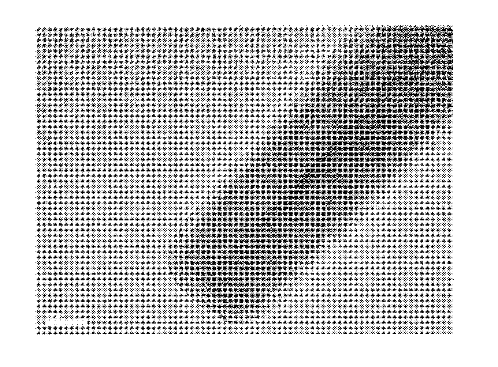
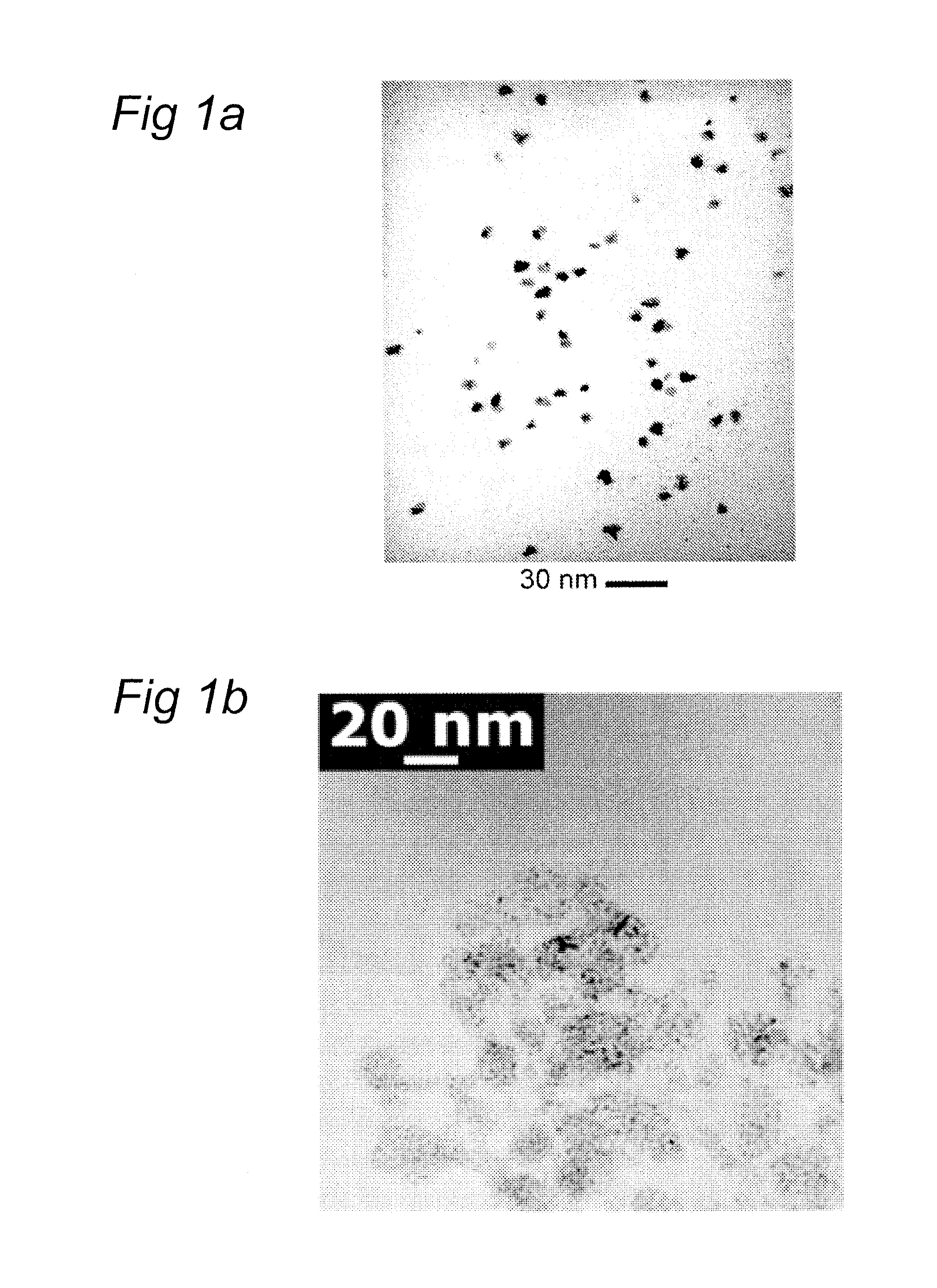
[0051]The platinum nanoparticles were characterized using transmission electron microscopy (TEM) and dynamic light scattering (DLS). Transmission electron microscopy (TEM) was accomplished using a Philips CM30T electron microscope with a lanthanum hexaboride (LaB6) filament operated at 300 kV as the source of electrons. Samples were mounted on a Qua...

example 1b

Synthesis of Carbon Nanotubes

[0054]The micro-emulsion containing 10 mM Pt precipitate was poured on a Copper grid, which was placed at the bottom of a reactor. After increasing the temperature to 973K (10 K / min) under a flow of nitrogen at 100 ml / min, ethylene gas (C2H4) was introduced at 10 ml / min into the reactor. The gas mixture passed through the reactor over the nanoparticles for 30 minutes at a constant temperature of 973K. Once the dwell step was over, the synthesis gas flow was stopped, and the reactor was cooled down to room temperature under nitrogen flow at 100 ml / min.

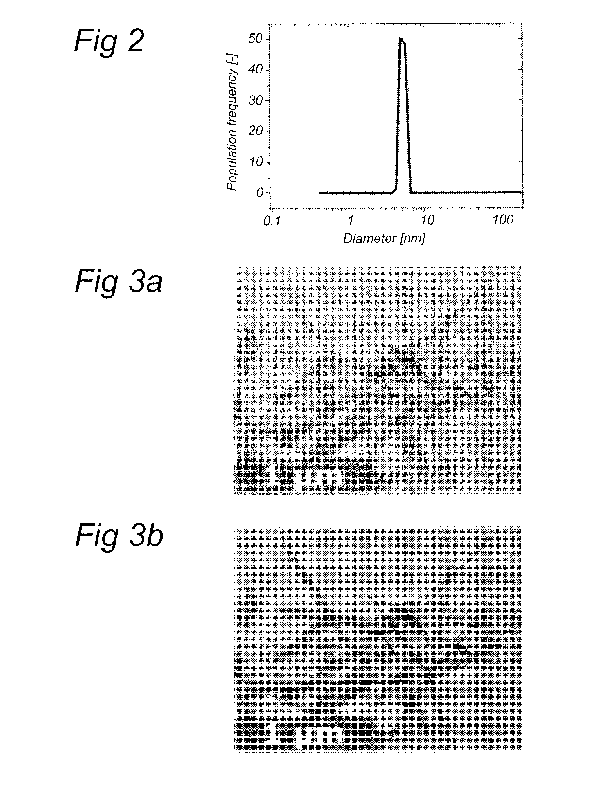
[0055]The carbon nanotubes thus obtained were characterized using electron microscopy (FIGS. 3-8), energy dispersive x-ray spectroscopy, dielectric spectroscopy (FIG. 9a), mechanical spectroscopy (FIG. 9b), Raman spectroscopy (FIG. 10) and nitrogen sorption (FIG. 11).

[0056]The tubes could be tuned to have a diameter from 5 to 50 nm and lengths from 100 nm to 3 microns. Each experiment resulted in nanotubes u...


PUM

PropertyMeasurementUnit
particle sizeaaaaaaaaaa
sizeaaaaaaaaaa

Abstract

The invention pertains to a method for manufacturing crystalline carbon nanostructures and / or a network of crystalline carbon nanostructures, comprising: (i) providing a bicontinuous micro-emulsion containing metal nanoparticles having an average particle size between 1 and 100 nm; (ii) bringing said bicontinuous micro-emulsion into contact with a substrate; and (iii) subjecting said metal nanoparticles and a gaseous carbon source to chemical vapor deposition, thus forming carbon nanostructures and / or a network of carbon nanostructures. Therewith, it is now possible to obtain crystalline carbon nanostructures networks, preferably carbon nanotubes networks.

Description

FIELD OF THE INVENTION[0001]The present invention relates to nanostructures of carbon such as carbon nanotubes (CNTs), fullerenes and graphenes. More particularly, the invention pertains to networks of carbon nanostructures, particular CNT networks, the production thereof, and the use of such networks in composite materials. The invention also pertains to compositions suitable for use in nanostructures network production.BACKGROUND OF THE INVENTION[0002]Carbon nanotubes are tubular structures formed by one or more layers of graphene. Since the discovery of a synthetic process to make carbon nanotubes in the early nineties, lot of attention has been concentrated on CNTs because of their excellent electrical, thermal and mechanical properties and large specific surface. Based thereon, all kinds of applications have been suggested, ranging from microelectronic components, displays, radio communication to fuel cells.[0003]There are three main approaches for the synthesis of single- and ...

Claims


Application Information

Patent Timeline
Patent Type & Authority Applications(United States)
IPC IPC(8): C01B31/02C01B31/00
CPCB01J21/185B01J23/42B01J35/0013B01J37/0238B01J37/16B82Y30/00Y10T428/256C01B31/0206H01M4/926H01M4/96C01B31/00C01B31/0226B82Y40/00C01B32/158Y10T428/31678B01J20/205C01P2002/82C09K5/14H01B1/04Y10S977/742Y10S977/753Y10S977/843C01B32/162Y02E60/50B01J35/23C01B32/168C01B32/186C08K3/04C09C1/44H01M4/9083H01M8/1004C01B32/15C01B32/00C01B32/16
Inventor KOWLGI, KRISHNA NARAYAN KUMARKOPER, GERARDUS JOSEPH MARIAVAN RAALTEN, RUTGER ALEXANDER DAVID
Owner CARBONX BV
Features
  • Generate Ideas
  • Intellectual Property
  • Life Sciences
  • Materials
  • Tech Scout
  • Unparalleled Data Quality
  • Higher Quality Content
  • 60% Fewer Hallucinations
Learn More