Thus, cooling reliability has become
mission critical to
refinery safety and profit and is affected by many factors such as environmental limitations on cooling water usage, environmental permits and inelastic supply chain pressures and variable refining margins.
In addition, these processes have tapped a great deal of the
cooling capacity reserve in the towers leaving some refineries “cooling limited” on
hot days and even bottlenecked.
Most U.S. refineries operate well above 90% capacity and thus, uninterrupted
refinery operation is critical to refinery profit and paying for the process upgrades implemented over the last decade.
Thus, if there is a shutdown of the
mechanical fan drive system associated with a particular
cell, then that
cell suffers a “
cell outage”.
A cell outage will result in a decrease in the production of refined petroleum.
For example, a “cell outage” lasting for only one day can result in the loss of thousands of refined barrels of petroleum.
If numerous cells experience outages lasting more than one day, the production efficiency of the refinery can be significantly degraded.
As more cell outages occur within a given
time frame, the percent loss in total
tower-cooling potential will increase.
This, in turn, will decrease product output and profitability of the refinery and cause an increase in the cost of the refined product to the
end user.
It is not uncommon for decreases in the output of petroleum refineries, even if slight, to cause an increase in the cost of
gasoline to consumers.
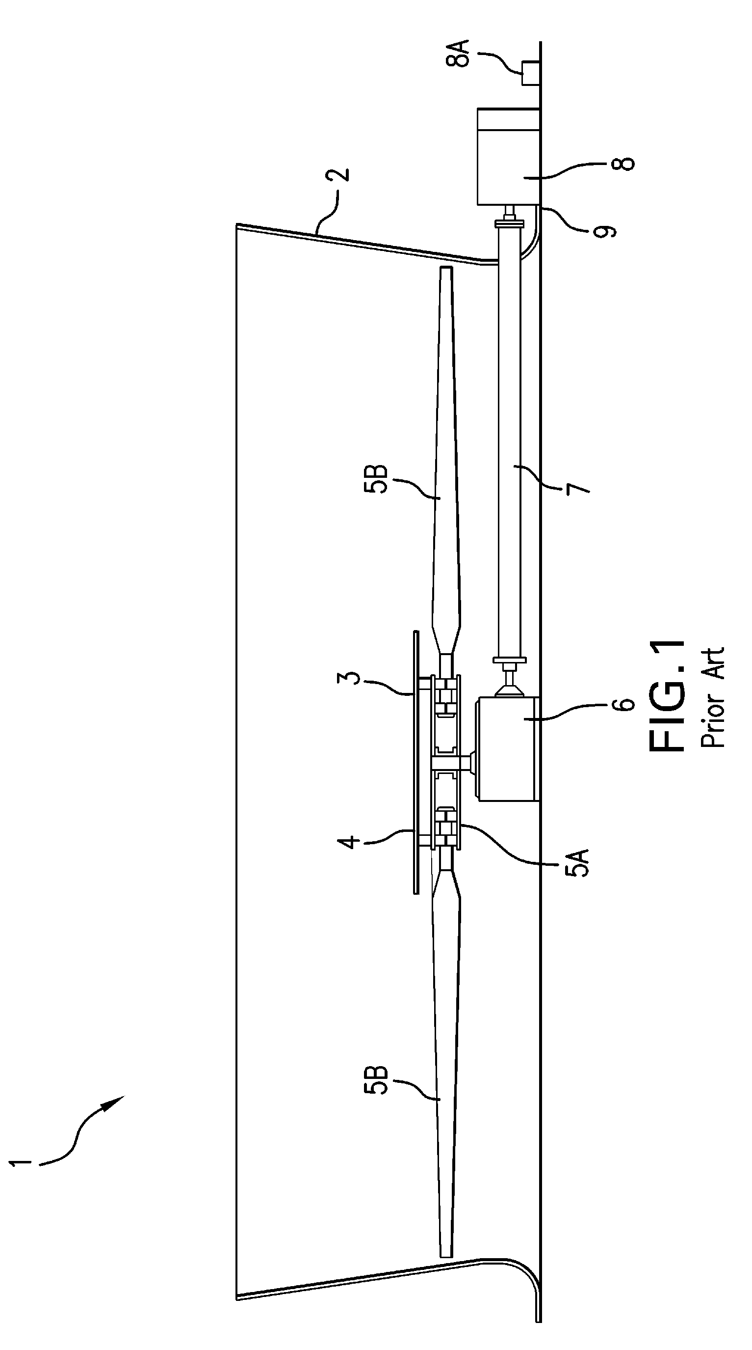
This prior art fan drive system is subject to frequent outages, a less-than-desirable MTBF (Mean Time Between Failure), and requires diligent maintenance, such as regular oil changes, in order to operate effectively.
Thus, the life cycle cost of the prior art
mechanical fan drive system compared to its initial purchase price is not equitable.
Once the
end user has purchased the more expensive
heavy duty and oversized components, the reliability of the prior art fan drive system is still quite poor even after they perform all the expensive and
time consuming maintenance.
Thus, this prior art gearbox-type drive system has a low,
initial cost, but a high cycle cost with poor reliability.
The loss in productivity over a period of time due to the poor reliability of the prior art
mechanical fan drive systems can be measured as a percent loss in refinery production (bbls / day).
Other types of prior art fan drive systems, such as V-
belt drive systems, also exhibit many problems with respect to maintenance, MTBF and performance and do not overcome or eliminate the problems associated with the prior art gearbox-type fan drive systems.
ACHEs lack the cooling effectiveness of “Wet Towers” when compared by size (a.k.a.
footprint).
Hydraulic motors have also been used with limited success.
Specifically, although hydraulic motors provide variable speed control, they have relatively low efficiencies.
However, belt drives, pulleys and right-angle gear boxes have poor reliability.
In particular, one significant problem with ACHE fan systems is the poor reliability of the belt due to belt tension.
The reliability deficiencies of the belt and
pulley systems and the gear
reducer systems used in the ACHE fan drive systems often result in outages that are detrimental to
mission critical industries such as petroleum refining, petro-chemical, power generation and other process intensive industries dependent on cooling.
Furthermore, the motor systems used in the ACHE fan drive systems are complex with multiple bearings, auxiliary oil and lubrications systems, complex valve systems for control and operation, and reciprocating parts that must be replaced at regular intervals.
Many petroleum refineries, power plants,
petrochemical facilities, chemical plants and other industrial facilities utilizing prior art ACHE fan drive systems have reported that poor reliability of
belt drive systems and right-angle drive systems has negatively affected production output.
These industries have also found that service and maintenance of the
belt drive and gearbox system are major expenditures in the life cycle cost, and that the prior art motors have experienced failure due to the incorrect use of
high pressure water spray.
Furthermore, since fan blades can become “fouled” or dirty in regular service and lose performance, many end-users water-wash their ACHE system to maintain their cooling performance.
However, directly exposing the ACHE system to
high pressure water spray can lead to premature maintenance and / or failure of system components, especially since prior art drive systems are typically open thereby allowing penetration by water and other liquids.
Prior art fan systems have further drawbacks.
However, the application of VFDs to induction motors has not been overly successful and not implemented on a wide scale due to poor success rates.
These applications have not been widely installed by end-users.
This issue is further exacerbated by “fan windmilling” which occurs when the fan turns in reverse due to the updraft force of the
tower on the
pitch of the fan.
Windmilling of the fan is not allowed due to the
lubrication limitation of gearboxes in reverse and requires the addition of an anti-reverse mechanism.
Such systems utilize lagging feedback loops that result in fan speed oscillation,
instability and speed hunting that consume large amounts of energy during abrupt speed changes and inertial changes which results in premature wear and failure of
gear train parts that are designed for single speed, omni-direction operation.
Induction motors in variable speed duty require extra insulation, additional windings and larger cooling fans for part-load cooling which increases the cost and size.
Application of induction motors on variable speed fans requires that the motor be able to generate the required torque to turn the fan to speed at part-load operation which can also require the motor to be larger than for a
steady state application and thus increase the cost and size.
Furthermore, motors and gearboxes are applied without knowledge of the
cooling tower thermal performance and operate only as a function of the basin temperature
set point which results in large speed swings of the fan wherein the fan speed is cycled from minimum fan speed to maximum fan speed over a short period of time.
The speed swings that occur at maximum fan acceleration consume significant amounts of energy.
The gear mesh of the gearbox is also a
limiting factor for reverse rotation as the loading on the gear mesh is not able to bear the
design load in reverse as it can in forward rotation.
End users in colder climates that require reverse rotation for de-
icing the cooling tower on cold days have reported numerous failures of the gearbox drive
train system.
Variable Speed Fan systems have not been widely adopted.
Currently operating cooling towers typically do not use expensive condition-monitoring equipment that has questionable reliability and which has not been widely accepted by the end users.
These vibration switches are isolated devices and are simply on-off switches that do not provide any kind of external signals or monitoring.
These vibration switches have poor reliability and are poorly applied and maintained.
Thus, these vibration switches provide no signals or information with respect to fan
system integrity.
Therefore, it is not possible to determine the source or cause of the vibrations.
Such vibration switches are also vulnerable to malfunction or poor performance and require frequent testing to assure they are working.
The poor reliability of these switches and their lack of fidelity to sense an impeding blade failure continues to be a safety issue.
In an alternate form, vibration switches have been installed on or in the gearbox itself but continue to suffer from a lack of vibration
signal fidelity and filtering to perform
condition monitoring and system shutdown to the satisfaction of the end-user and their wide spread application.
Most refinery operators operate without any measure of performance and therefore wait too long between service and maintenance intervals to correct and restore the performance of the cooling tower.
It is not uncommon for some end-users to operate the tower to failure.
Some end-users test their cooling towers for performance on a periodic basis, typically when a cooling tower is exhibiting some type of cooling performance problem.
Furthermore, these tests do not provide any trending data (multiple test points), load data or long-term data to establish performance, maintenance and service criteria.
For example, excessive and wasted
energy consumption occurs when operating fans that cannot perform effectively because the fill is clogged thus allowing only partial
airflow through the tower.
Poor cooling tower performance can result in unscheduled
downtime and interruptions in production.
In many prior art systems, it is not uncommon for end-users to incorrectly operate the cooling tower system by significantly increasing electrical power to the fan motors to compensate for a clogged tower or to increase the
water flow into the tower to increase cooling when the actual corrective action is to replace the fill in the tower.
Poor cooling tower performance can lead to incorrect operation and has many negative side effects such as reduced cooling capability, poor reliability,
excessive energy consumption, poor
plant performance, and decrease in production and safety risks.


