
Microstructured high-temperature hybrid material, its composite material and method of making

a hybrid material and microstructure technology, applied in the field of hybrid materials, can solve the problems of weak interface between adjoining constituents, a challenge to the development of composite materials, and the individual constituents cannot provide the properties of the individual constituents, and achieve the effect of strength, stiffness and ability

Inactive Publication Date: 2015-12-31
CHUNG DEBORAH D L
View PDF5 Cites 45 Cited by
  • Summary
  • Abstract
  • Description
  • Claims
  • Application Information

AI Technical Summary

Benefits of technology

This patent describes a hybrid material that exhibits strength, stiffness, and resistance to high temperatures. The hybrid material consists of two components, A and B, which are derived from different materials. The component A is made up of inorganic compounds, oxides, carbides, nitrides, and borides, while the component B is made up of elemental carbon, inorganic compounds, and organic compounds. The components have specific shapes and sizes, with the short dimension of each unit being perpendicular to the long dimension. The hybrid material has been found to have superior properties compared to materials made from either component alone.

Problems solved by technology

The combination results in properties that none of the individual constituents can provide.
A challenge in the development of hybrid materials relates to the imperfect bonding between the constituents of the hybrid material.
The imperfect bonding results in weakness at the interface between the adjoining constituents.
The smaller is the constituent unit size, the larger is the amount of the interface area per unit volume, and the more severe is the problem associated with the weak interface.
This requirement on the binder or matrix poses a challenge for the development of composite materials.
Another challenge in the development of composite materials relates to the imperfect binding of the solid ingredients of the composite material.
The imperfect binding results in weakness at the interface between the units of a solid ingredient and the matrix of the composite.
The smaller is the size of each unit of the solid ingredient, the larger tends to be the amount of the interface area per unit volume, and the more severe tends to be the problem associated with the weak interface.
In case that the elemental carbon in the graphite family is not crystalline, the carbon still consists of layers that exhibit a combination of covalent bonding and metallic bonding within each layer, but the layers are limited in area and are not well ordered.
Although elemental carbon in the graphite family is a high-temperature material, it suffers from the tendency to be oxidized at high temperatures in the presence of oxygen, such that the carbon forms carbonaceous gases, such as carbon dioxide.
As a consequence of the oxidation, the elemental carbon experiences mass loss, which is undesirable.
However, the coating tends to suffer from the tendency to be detached, due to the high-temperature use and the difference in thermal expansion coefficient between the coating material and the carbon material.
Furthermore, the coating process adds to the cost of material production.
In addition, due to the low thermal conductivity and low electrical conductivity of typical ceramic materials compared to elemental carbon materials, the ceramic coating is undesirable for applications that require heat dissipation, lightning protection, electromagnetic interference shielding or electrical conduction.
Both ceramic materials and elemental carbon materials are typically brittle compared to metals.
However, the temperature required for sintering is still very high.
Furthermore, sintering is expensive and restrictive in the size of the resulting article, due to the high temperatures and pressures involved.
Pores are detrimental to the mechanical properties and numerous other properties of the resulting ceramic or carbon material.
The densification process is tedious and costly and contributes significantly to the high cost of ceramic-matrix and carbon-matrix composites.
However, this method does not provide enough positive effects on the mechanical properties.
However, they tend to be more difficult to fabricate than carbon-matrix composites, due to the greater complexity of the chemical / thermal process associated with the conversion of a ceramic precursor to a ceramic compared with the process associated with the conversion of a carbon precursor to elemental carbon.
In other words, there is no control of the configuration of the spatial distribution of the phases in the multi-phase material.
This means that there is no control of the shape of the units of each phase in the multi-phase material.
Furthermore, this method limits the choice of the ceramic phase in the multi-phase material to those that can be formed by processing ceramic precursors that are in a liquid form.
In particular, ceramic alloys such as mullite (which exhibits an attractively high melting temperature) cannot be obtained by using this method.
However, this method also suffers from the difficulty of forming specific ceramic alloys and the difficulty of controlling the configuration of the hybrid.
This form of ceramic-carbon hybrid is limited to the configuration in which the two types of fibers are bound together by a certain matrix material, such that the fibers are substantially not in direct contact.
In the absence of the matrix material, the hybrid does not exhibit adequate mechanical properties, due to the air gaps between the adjacent fibers.
This method suffers from the fact that the ceramic in the hybrid is limited to silicate hydrates, which, partly due to their porosity (as in cement), tend to be inferior to conventional ceramics (such as alumina, silicon carbide, silicon dioxide and mullite) in the mechanical properties.
Therefore, the choice of reinforcement is limited to reinforcement materials that can withstand high temperatures.
This limitation reduces the flexibility of composite material design.
Furthermore, due to the relatively high cost of reinforcements that can withstand high temperatures, this limitation adds cost to the composite material.
However, this method does not provide adequate positive effects on the mechanical properties and does not facilitate the densification process.
However, the filamentous shape of a carbon nanotube is not optimum for providing a large interfacial area.
In addition, carbon nanotube is very expensive compared to ceramic particles.
Furthermore, this method does not facilitate the densification process.
However, this method does not provide adequate positive effects on the mechanical properties, and does not facilitate the densification process.

Method used


Image

  • Microstructured high-temperature hybrid material, its composite material and method of making
  • Microstructured high-temperature hybrid material, its composite material and method of making
  • Microstructured high-temperature hybrid material, its composite material and method of making

Examples


example 1

Ingredients

[0095]This example describes the ingredients used for evaluation of the invented materials in comparison with competing materials.

[0096]Organo-modified clay (called organoclay, also called nanoclay) is manufactured by modifying clay with quaternary ammonium cations via a cation exchange process. The organoclay used is a natural montmorillonite that has been intercalated with a quaternary ammonium salt (dimethyl, dihydrogenated tallow) with chloride anions. Montmorillonite constitutes 90% of the composition of an industrial grade bentonite. The basal spacing d001=31.5 Å, as shown by X-ray diffraction (XRD). The particles are white (more exactly, off white) and have a feathery morphology.

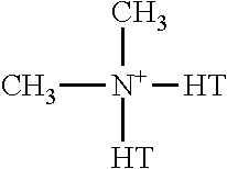
[0097]The molecules that constitute the organic component in the organoclay are of the form

The hydrogenated tallow (abbreviated HT in the schematic above) in the ammonium cation involves ˜65% fatty acids with 18 carbon atoms in the alkyl carbon chain in each molecule, ˜30% fatty acids with ...

example 2

Carbon-Carbon Composite Fabrication Method

[0102]This example describes the method used for the fabrication of carbon-carbon (abbreviated C / C) composites. The ingredients are as described in Example 1.

[0103]The organoclay and pitch powder in the mass ratio of 1:4 are dry mixed in a ball mill (without grinding balls) for 24 h for the purpose of initial mixing. Then the mixture is dispersed in water that contains 0.1 wt. % dissolved PEO, such that the dispersion contains 10 wt. % organoclay-pitch mixture. The dispersion is stirred manually for 10-20 min, followed by 2.0 h of magnetic stirring, in order to achieve an adequate degree of mixing. The carbon fiber tow is immersed in the dispersion for 3.0 h in order for the tow to be coated with the organoclay-pitch mixture.

[0104]The mass ratio of the immersed fibers to pitch (in the dispersion) to organoclay (also in the dispersion) is 50:40:10. This proportion is such that the entirety of the liquid-based dispersion is consumed in coating...

example 3

Ceramic-Carbon Hybrid Material Fabrication Method

[0108]This example describes the method of fabricating a ceramic-carbon hybrid material. The ingredients are as described in Example 1.

[0109]Clay particles in the amount of 4.00 g (unless stated otherwise) are hot-pressed in the absence of any other ingredient, using the same graphite mold and the same process as in Example 2. Two types of clay particles are used, namely organoclay and sodium bentonite (without an organic component), in order to investigate the effect of the organic component. Either type of clay is placed in the graphite mold under a nitrogen purge at a flow of 70 ml / min.


PUM

PropertyMeasurementUnit
temperatureaaaaaaaaaa
pressureaaaaaaaaaa

Abstract

This invention provides a hybrid material that exhibits strength, stiffness and ability to resist high temperatures. This hybrid material essentially consists of component A and component B. Component A is selected from the group consisting of inorganic compounds, oxides, carbides, nitrides, borides, and combinations thereof. Component B is selected from the group comprising elemental carbon, inorganic compounds, oxides, carbides, nitrides, borides, and combinations thereof. Component B comprises a plurality of units, each of the units substantially exhibiting a shape, such that this shape substantially exhibits a long dimension and a short dimension, with the short dimension being in a direction that is essentially perpendicular to the direction of the long dimension and the short dimension being in the range from 0.1 nm to 0.5 μm. Each of the units of component B is substantially in contact with and substantially bonded to at least one of the units of component A.

Description

FIELD OF THE INVENTION[0001]This invention relates to the field of hybrid materials.BACKGROUND OF THE INVENTION[0002]Hybrid materials refer to artificial combinations of constituents that differ in structure and / or composition. The combination results in properties that none of the individual constituents can provide. The structure and composition within each constituent, the degree of bonding between the constituents, the relative positions of the units of the constituents in the hybrid material, and the shape and size of each unit of the constituent in the hybrid material are all important in governing the properties of the hybrid material. An example of a hybrid material is one that consists of two constituents that are bonded together within each unit of the hybrid material, with each constituent comprising a plurality of units, such that each unit is in the form of a sheet. In an example of the relative positions of the units of the constituents, the sheets of the two constitue...

Claims


Application Information

Patent Timeline
Patent Type & Authority Applications(United States)
IPC IPC(8): C04B33/02
CPCC04B33/326C04B35/62849C04B35/645C04B35/83C04B2235/3201C04B2235/349C04B2235/422C04B2235/5248C04B2235/5264C04B2235/6562C04B2235/6567C04B2235/661C04B2235/77C04B2235/80C04B2235/96
Inventor CHUNG, DEBORAH D.L.GAO, XIAOQING
Owner CHUNG DEBORAH D L
Learn More