Method and Apparatus for Surface Chemical Functionalization of Powders and Nanoparticles

a technology powder, applied in the field of surface chemical functionalization of powders and nanoparticles, can solve the problems of affecting processing, material degradation, and material quality, and affecting the processing quality,

Active Publication Date: 2016-02-11
KETTERING UNIVERSITY
View PDF1 Cites 3 Cited by
  • Summary
  • Abstract
  • Description
  • Claims
  • Application Information

AI Technical Summary

Benefits of technology

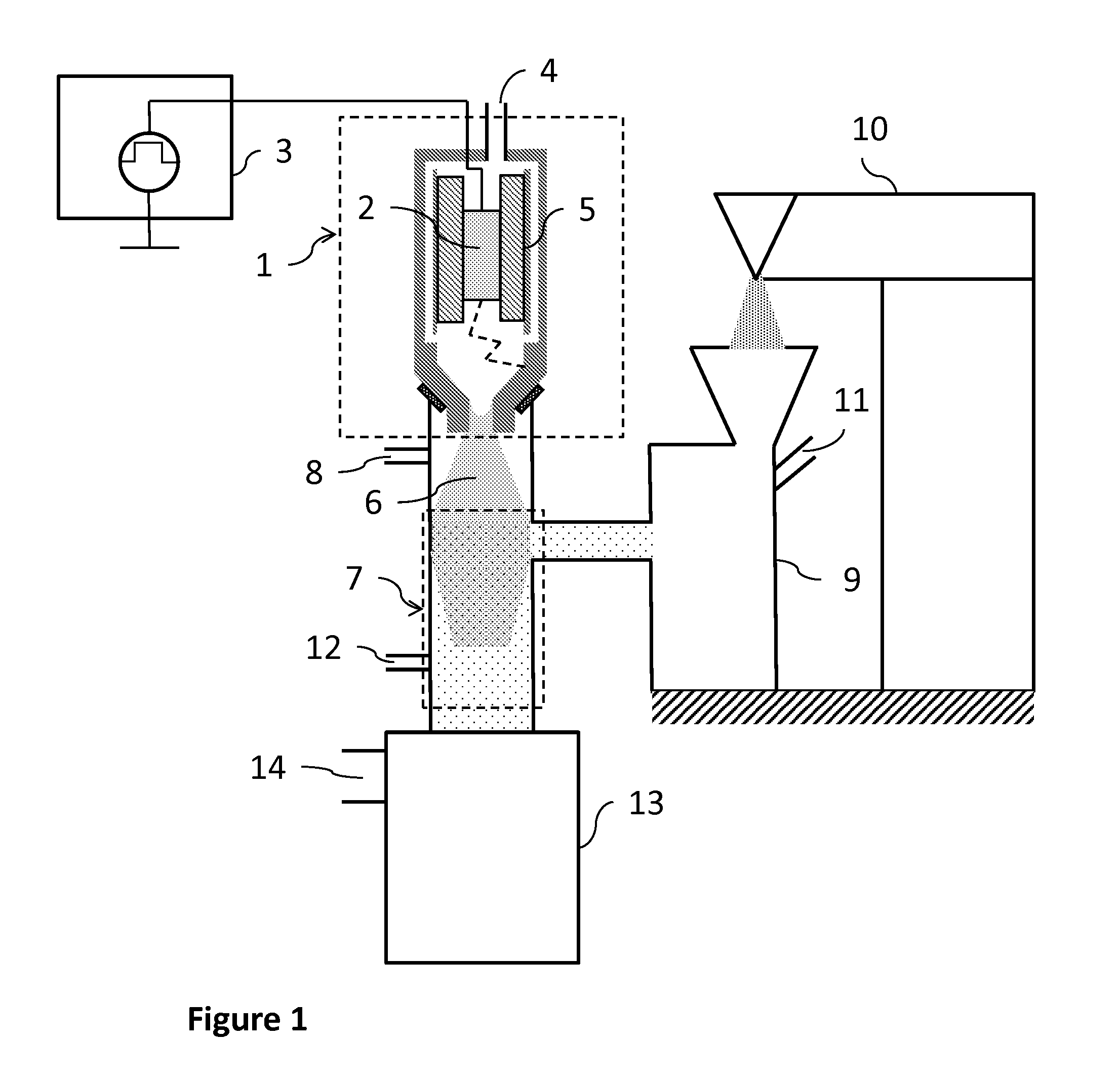
[0012]In overcoming the enumerated drawbacks and other limitations of the related art, the present invention provides an atmospheric plasma chemical surface modification process for solid low micron and sub-micron particles that imparts new chemical functional groups or grafted molecules onto the surface of the particles. The process is fast, continuous, low temperature, and brings about uniform surface modification. The method generally comprises providing a low temperature atmospheric plasma jet, transport of separated and de-agglomerated particles for modification, an optional injection of precursor chemical or chemical species

Problems solved by technology

Plasma treatment of powders and particles inherently presents challenge for uniformly treating all exposed surfaces of the particles given the high surface area compared to larger sheets and parts.
Some materials, especially organic and polymeric materials, are more susceptible to degradation in a plasma environment and can degrade upon exposure or after prolonged exposure to high energy ions and other species in a plasma environment.
When the particles are located in the plasma generation area within an electric field, detrimental damage can occur from high temperatures, ion bombardment, filamentary discharges, and generally excessive treatment.
Furthermore, the particles can coat the surfaces of the electrodes used to generate the plasma over time, negatively impacting the processing.
The current technologies include those in which the particles are placed in an electric field where surface charging, high temperatures, and ion bombardment that can bring about undesirable d

Method used


Image

  • Method and Apparatus for Surface Chemical Functionalization of Powders and Nanoparticles
  • Method and Apparatus for Surface Chemical Functionalization of Powders and Nanoparticles
  • Method and Apparatus for Surface Chemical Functionalization of Powders and Nanoparticles

Examples


example 1

[0044]In this example, polytetrafluoroethylene (PTFE) particles from I. E. du Pont de Nemours and Company, 25 micron, are treated according to one aspect of the present disclosure using an apparatus similar to that shown in FIG. 1. The atmospheric pressure plasma device (Diener electronic GmbH+Co. KG, Germany) is comprised of a radio frequency RF power source operating at 20 kHz, 230 V, and 300 W. Air and nitrogen are used as the ionization gas and have a flow rate approximately 1,500 L / hr (standard temperature and pressure). Chemical precursors are added upstream from the treatment zone and consist of steam and a vaporized solution of 10% (hydroxyethyl)methacrylate (HEMA) in deionized (DI) water with flow rates ranging from 0-2 g / min. A jet mill disperser (Fluid Energy Processing & Equipment Co., Telford, Pa.) is used to disperse the particles into a carrier gas of nitrogen at 85 psig and the particles are transported through the system at a rate of approximately 2 g / min. Collectio...

example 2

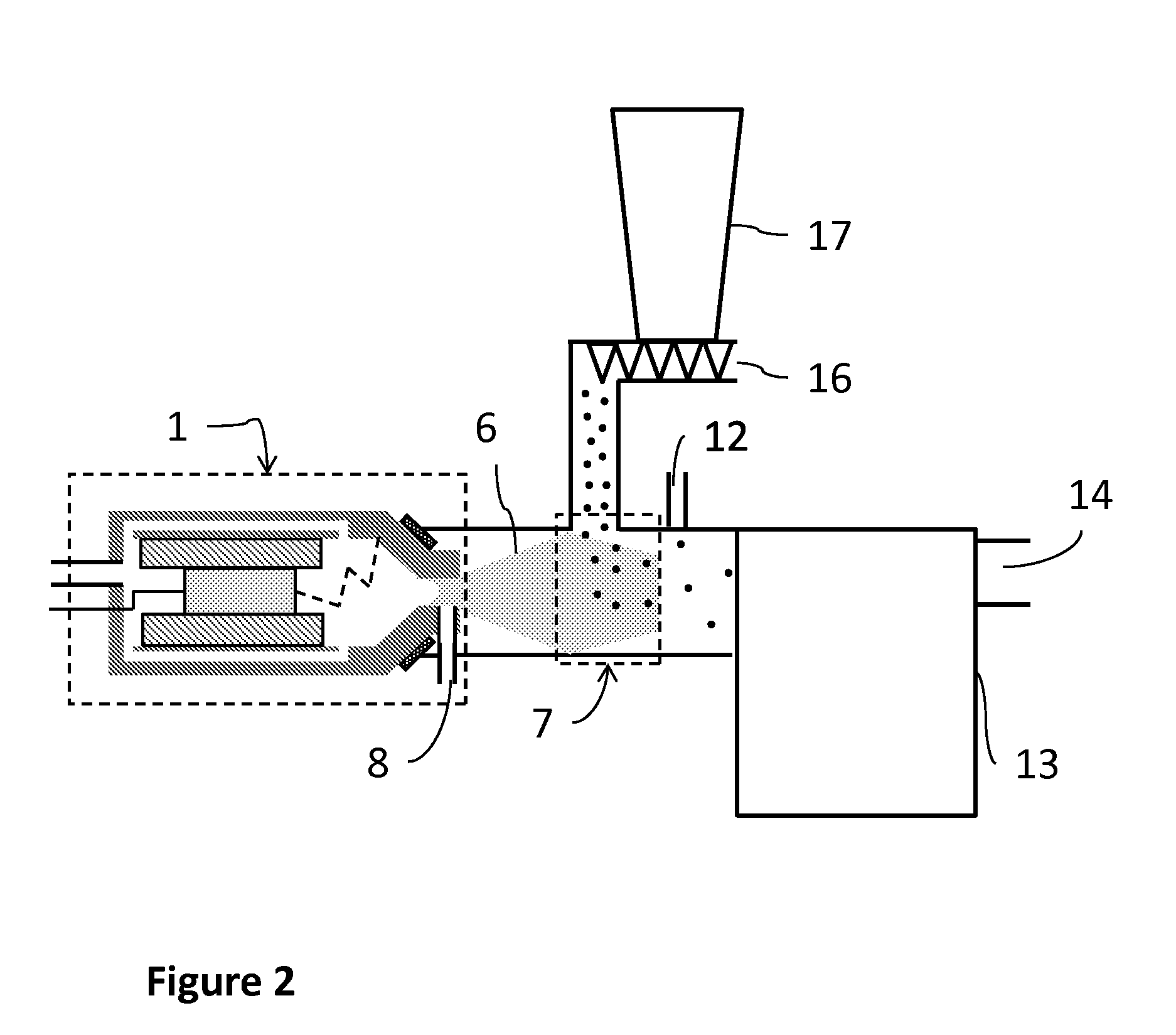
[0047]In this example, polypropylene (PP) micro-sized particles of size 350 micron (Sigma Aldrich) are treated according to the teachings of the present invention. The atmospheric pressure plasma device is comprised of a pulsed DC power source (Plasmatreat GmbH, Germany) operating under conditions of 250-350 V, 3.7-4.1 Amps, a pulse frequency of 20-21 kHz, and a duty cycle of 90-100% with dry air as the carrier gas flowing at 1800 L / hr. The reactor configuration used in this example included feeding the polypropylene particles through a narrow channel with the transport driven by gravity, similar to FIG. 2. Deionized (DI) water and a solution of 10% HEMA in DI water are used as the chemical precursor and delivered at a rate ranging from 1-10 g / min into the plasma treatment zone. The treated particles are collected using DI water delivered in a port downstream of the treatment zone via a spray apparatus with nitrogen as a carrier gas to separate the treated particles and collect as a...

example 3

[0051]In this example, polymethylmethacrylate (PMMA) micro-sized particles of size 250 micron (Sigma-Aldrich Co. LLC) are treated according to the teachings of the present invention. The atmospheric pressure plasma device (Plasmatreat GmbH, Germany) is comprised of a pulsed DC power source operating under conditions of 250-350 V, 3.7-4.1 Amps, a pulse frequency of 20-21 kHz, and a duty cycle of 90-100% with dry air as the carrier gas flowing at 1800 L / hr. The reactor configuration used in this example included feeding the PMMA particles through a narrow channel with the transport driven by gravity, similar to FIG. 2. Deionized (DI) water and a solution of 10% HEMA in DI water are used as the chemical precursor and delivered at a rate ranging from 1-10 g / min into the plasma treatment zone. The treated particles are collected using DI water delivered in a port downstream of the treatment zone via a spray apparatus with nitrogen as a carrier gas to separate the treated particles and co...


PUM

PropertyMeasurementUnit
Forceaaaaaaaaaa
Pressureaaaaaaaaaa
Hydrophilicityaaaaaaaaaa

Abstract

A method and apparatus is provided for the modification of the surface chemistry of solid nano- and micro-particles in order to tailor the properties and functions of these particles. The method generally involves the generation of an atmospheric plasma glow discharge and energetic species that undergo chemical reaction with the surface of the primary particles. The process includes the generation of energetic species to initiate reaction, optional delivery of a precursor fluid, optional delivery of chemical species for grafting, and delivery of separated and de-agglomerated particles into the plasma discharge exiting the plasma generation chamber.

Description

[0001]This disclosure relates generally to a method and apparatus for modification of the surface chemistry of solid nanoparticles and microparticles to tailor the properties and functions of these particles. More specifically, the invention describes a method involving the generation of an atmospheric plasma glow discharge and energetic species that undergo chemical reaction with the surface of the primary particles. The invention also describes a method to graft chemical species onto the surface of the particles through creation of reactive sites on the surfaces that react with added chemical species. The invention also describes an apparatus comprising an atmospheric pressure plasma process with said process including the generation of energetic species to initiate reaction, optional delivery of a precursor fluid, optional delivery of chemical species for grafting, and delivery of separated and de-agglomerated particles into the plasma discharge exiting the plasma generation cham...

Claims


Application Information

Patent Timeline
IPC IPC(8): C08J3/24
CPCC08J3/24C08J2333/12C08J2323/12C08J2327/18C08J3/124
Inventor GILLIAM, MARYFARHAT, SUSANGARNER, GRAHAMMAGYAR, MICHAEL
Owner KETTERING UNIVERSITY
Why Eureka
Try Eureka