
LED driven plasmonic heating apparatus for nucleic acids amplification

a plasmonic heating and nucleic acid technology, applied in biochemistry apparatus and processes, laboratories glassware, etc., can solve the problems of high cost of lasers and detection systems, inability to perform poc testing, and inability to meet the needs of poc testing, etc., to achieve low power consumption, low power consumption, and easy use

Active Publication Date: 2018-03-22
RGT UNIV OF CALIFORNIA
View PDF1 Cites 9 Cited by
  • Summary
  • Abstract
  • Description
  • Claims
  • Application Information

AI Technical Summary

Benefits of technology

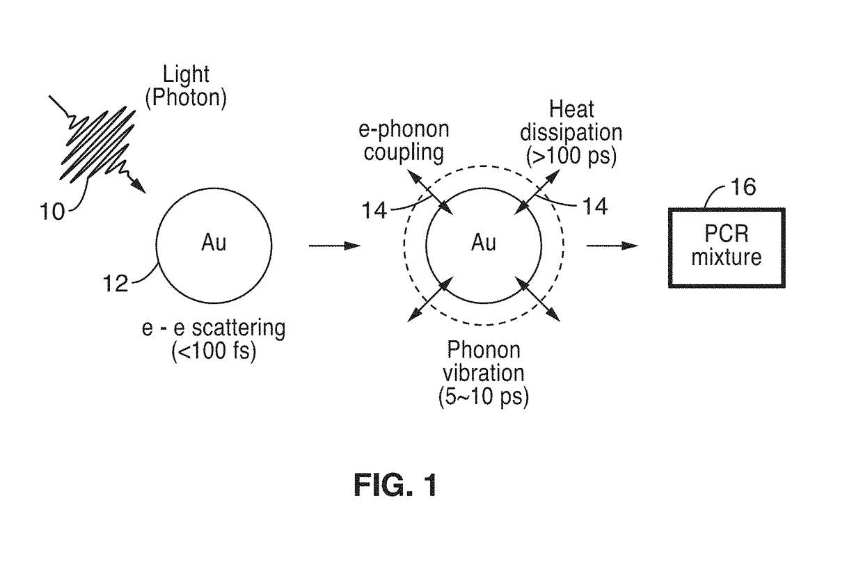
This patent describes a system and method for nucleic acid amplification and quantification using polymerase chain reaction (PCR) for various applications such as clinical laboratories, precision medicine, personalized medicine, agricultural science, forensic science, and environmental science. The patent describes an ultrafast PCR method using plasmonic photothermal light-to-heat conversion, which allows for timely diagnosis at the point-of-care. The technical effects of the patent include the use of a thin gold film for efficient photonic heat conversion, resulting in rapid heating and cooling of the surrounding solution to over 150°C within 3 min. The method allows for ultrafast thermal cycling from 55°C to 95°C in 5 minutes, successful nucleic acid amplification, and the use of low cost LEDs and a simple plasmonic heater fabrication process. The invention offers a low-cost, portable, and simple thermal cycler with low power consumption for point-of-care diagnostics.

Problems solved by technology

While commercial PCR systems are improving heating and cooling rates to reduce amplification time, they are still relatively time-consuming (typically requiring an hour or more per amplification).
However, existing systems are not suitable for POC testing due to high power consumption, heavy weight require a complicated fabrication process, prone to human error, require expensive lasers and detection systems, or have reliability issues.

Method used


Image

  • LED driven plasmonic heating apparatus for nucleic acids amplification
  • LED driven plasmonic heating apparatus for nucleic acids amplification
  • LED driven plasmonic heating apparatus for nucleic acids amplification

Examples


example 1

[0057]a. Fabrication

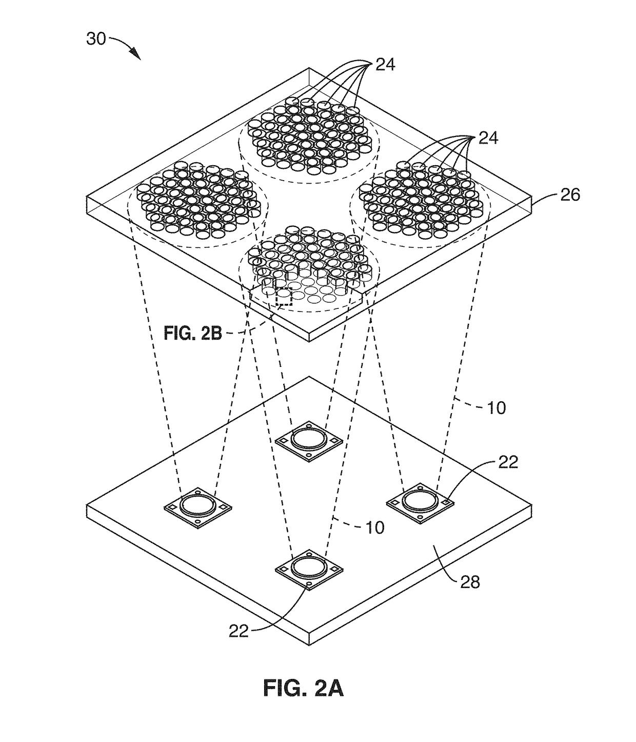
[0058]Several 4 mm-thick poly(methyl methacrylate) (PMMA) sheets 26 were cut with a VersaLASER VL-200 laser cutting system (Universal Laser System, Inc.) to make reaction wells 24 with a 4 mm diameter. A 1.5 mm-thick bottom PMMA sheet were attached to the top sheet containing reaction wells were bonded together using the thermal bonding. Thermal bonding was performed at 84° C. with pressure of 1.0 metric ton after UV / Ozone treatment of PMMA sheet for 10 min. The thin Au films 20 of different thicknesses were deposited by electron beam evaporation under base pressure of 2×10⁻⁷ Torr. The thin Au film 20 was then passivated with thin poly(dimethylsiloxane) (PDMS) by dropping 3 μL of PDMS into the well and curing in the oven for 2 hrs to prevent PCR reaction inhibition by the thin Au film and thermocouple.

[0059]b. Simulation

[0060]COMSOL Multiphysics software (Ver. 4.3) was used for performing simulations. The detailed geometry and materials properties for simulation ...

example 2

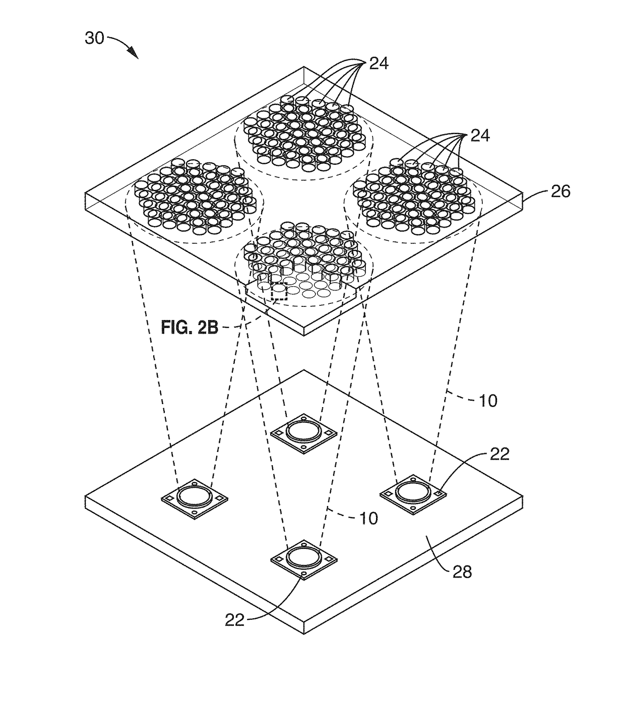
[0083]FIG. 11 shows the schematics of experimental set up 50 for LED driven plasmonic heating of thin Au films. Blue LEDs 22 with 447.5 nm peak wavelength were used for light illumination and the light from LEDs was focused by commercially available plastic lens 32. The thin Au films 20 with nanometer sized grain were deposited by an electron beam evaporation method. The surface temperature of liquid 16 was measured by long wavelength infrared (LWIR) camera 52.

[0084]FIG. 12 shows the demonstration of fast thermal cycle using 2 μL of glycerol from 50° C. to 90° C. for 9 min using LED driven plasmonic heating of thin Au films. The injection current was 1 A, and the thickness of thin Au film was 56 nm.

[0085]FIG. 13A shows the temperature changes of liquid with different thin Au films thickness. As the thickness of Au film increase, the maximum temperature of liquid is increased, as shown in FIG. 13B. The temperature of liquid was rapidly decreased after turn off of LEDs.

[0086]FIG. 13C ...


PUM

PropertyMeasurementUnit
temperatureaaaaaaaaaa
power consumptionaaaaaaaaaa

Abstract

Systems and methods for plasmonic heating by combined use of thin plasmonic film-based 2D and 3D structures and a light-emitting diode (LED) for nucleic acids amplification through fast thermal cycling of polymerase chain reaction (PCR) are described.

Description

CROSS-REFERENCE TO RELATED APPLICATIONS[0001]This application is a 35 U.S.C. § 111(a) continuation of PCT international application number PCT / US2016 / 013732 filed on Jan. 15, 2016, incorporated herein by reference in its entirety, which claims priority to, and the benefit of, U.S. provisional patent application Ser. No. 62 / 104,574 filed on Jan. 16, 2015, incorporated herein by reference in its entirety. Priority is claimed to each of the foregoing applications.[0002]The above-referenced PCT international application was published as PCT International Publication No. WO 2016 / 115542 on Jul. 21, 2016, which publication is incorporated herein by reference in its entirety.STATEMENT REGARDING FEDERALLY SPONSORED RESEARCH OR DEVELOPMENT[0003]Not ApplicableINCORPORATION-BY-REFERENCE OF COMPUTER PROGRAM APPENDIX[0004]Not ApplicableNOTICE OF MATERIAL SUBJECT TO COPYRIGHT PROTECTION[0005]A portion of the material in this patent document is subject to copyright protection under the copyright la...

Claims


Application Information

Patent Timeline
Patent Type & Authority Applications(United States)
IPC IPC(8): C12Q1/68B01L7/00B01L3/00
CPCC12Q1/686B01L7/52B01L3/50851B01L2300/1861B01L2200/147B01L2300/168B01L2300/0896B01L2300/0829B01L2300/0636C12Q2565/628B01L2200/0663B01L2300/0654B01L2300/1855
Inventor LEE, LUKE P.SON, JUN HOCHO, BYUNGRAE
Owner RGT UNIV OF CALIFORNIA
Learn More