Process for rapidly manufacturing ultrasmall phase-change vo2 nanomaterial

a nanomaterial and phase-change technology, applied in the field of organic nanoparticles, can solve the problems of poor material quality control, potential explosion hazards, and tepid adoption of these materials, and achieve the effects of reducing product cost, facilitating product-water separation, and small nanoparticles

Pending Publication Date: 2022-08-04
UCHICAGO ARGONNE LLC
View PDF3 Cites 0 Cited by
  • Summary
  • Abstract
  • Description
  • Claims
  • Application Information

AI Technical Summary

Benefits of technology

[0018]Yet another object of the present invention is to provide a continuous method for producing functionalized VO2 particles. A feature of the invention is dissolving organic material in super critical fluid entraining the particles. An advantage of this process is that it coats the particles and facilitates product-water separation. This reduces product cost, and is further reduced if artificial intelligence is utilized in the mixing and separating process.
[0019]Another object of the present invention is to provide a method for generating particular size nanoparticles for use in thermochromic applications. A feature of the invented method is the use of confined jets or a heated fluid distributor. In the invented system, supercritical fluid such as water readily provides enough heating energy. Heating speed is largely determined by how well / quick super critical water can be mixed into a cold precursor stream. An advantage of the method is that smaller nanoparticles are generated compared to state of the art counter-current flow paradigms.
[0020]Still another object of the present invention is to provide a method to obtain pure M-VO2. A feature of the invention is maintaining a uniform high temperature field. One means for doing this is by operating inside a heated furnace to prevent the formation of local cold spots near the reaction wall regions in reaction environments. An advantage of the invention is the prevention of the formation of B or A-phase VO2.
[0021]Another object of the present invention is to provide a pure M-phase VO2 nanoparticle and a method for producing such a purified nanoparticle. A feature of the invention comprises hydrothermically heating a suspension containing V4+ precursor to between about 300° C. and about 500° C. to provide a uniform temperature field. In an embodiment of the invention, heating with primary supercritical water occurs in the center of the reactor, thereby virtually eliminating contact of nanoparticles produced with the walls of the reactor. The inventors estimate that between 0 and 5 percent of the nanoparticles produced contact the reactor walls, often between 2 and 5 percent and usually no more than 2 percent. An advantage of the invention is that the purification process prevents the generation of low-temperature phases (i.e. A or B phase VO2) or mixed phase VO2 nanoparticle materials.
[0022]Briefly, the invention provides a method for continuously producing nanoparticles, the method comprising: heating a precursor mixture with supercritical fluid (such as water), wherein the mixture contains a first compound capable of being nucleated into nanoparticles which can be a tetragonal rutile crystal state, or may transition from a monoclinic to a tetragonal rutile crystal state; tuning flowrate of heating fluid and thus particle residence time to control particle growth and size; cooling the heated mixture to stop the particle growth and obtain core particles of a predetermined shape and size; and encapsulating the core particles with an organic material.
[0023]Also provided is a device for continuously synthesizing composite nanoparticles, the device comprising a fluid supply and a precursor supply; a means for heating the fluid, a continuous flow hydrothermal reaction chamber adapted to receive the heated water and precursor, a means for chilling the heated water and precursor, and a capping agent supply positioned downstream of the reaction chamber.

Problems solved by technology

However, adoption of these materials remains tepid due to a lack of efficient manufacturing processes for making same.
Existing batch processes for the manufacturing of large-volume nanoparticles (i.e., between 20 nm and 30 nm in diameter) are time consuming (often taking days) and result in poor material quality control.
These processes are associated with potential explosion hazards and high product costs.
For example, for applications in the dynamic window film market, the fabrication of electrochromic windows is expensive.
Methods of fabrication for high performance nanocomposite thermochromic dynamic windows which incorporate nanoparticles typically require harsh reaction conditions.
As noted supra, fabrication is in batch mode, thereby resulting in inconsistent quality between batches.
State of the art nanoparticle fabrication protocols embody limited controllability for synthetic conditions, such as mixing, heat and mass transfer.
Reactor explosion hazards are also present.
Also, batch systems are poorly scalable, and require large footprints.
Resulting product is expensive.
Due to the challenge with working with multivalent vanadium which exhibits various stable oxidation states (V2+, V3+, V4+, V5+) in addition to its many polymorphs (B-, A-, M-, D-, and P-phase), the processing techniques are simply too complicated, requiring multiple steps that also consume time and energy.
This is still too long since it results in the generation of large size (e.g., above 150 nm in diameter) nanoparticles per agglomeration mechanism.
In addition, some CFHT processes are not successful in directly obtaining M-phase VO2 in a single step.
Generally, in state of the art continuous flow systems, size, morphology, and phase structure of the VO2 particles have not been well controlled.
This is largely caused by limited mixing between the heating fluid and the reactant stream.
This results in not obtaining the right phase (M-phase), or the generation of larger than desired particles.

Method used


Image

  • Process for rapidly manufacturing ultrasmall phase-change vo2 nanomaterial
  • Process for rapidly manufacturing ultrasmall phase-change vo2 nanomaterial
  • Process for rapidly manufacturing ultrasmall phase-change vo2 nanomaterial

Examples


example

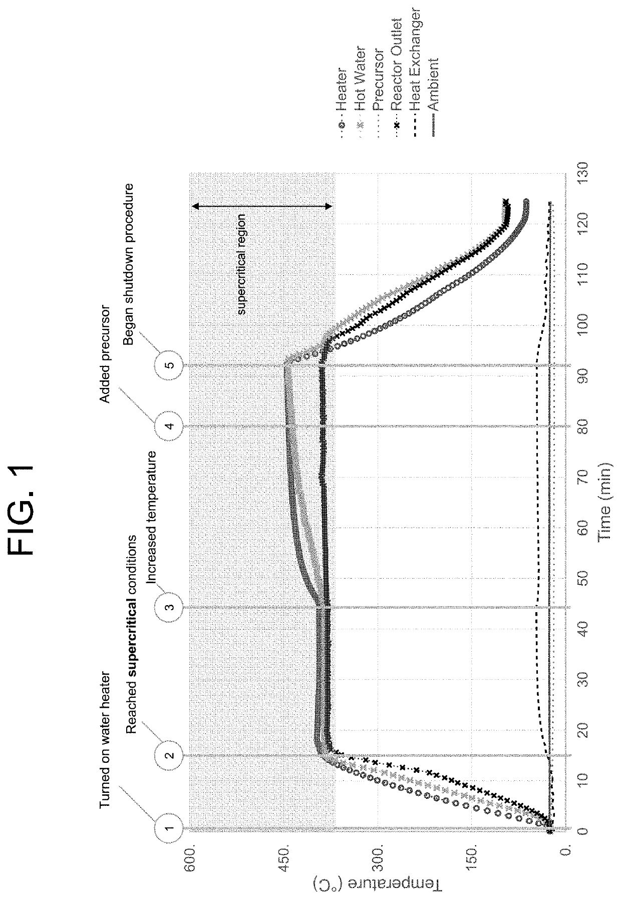
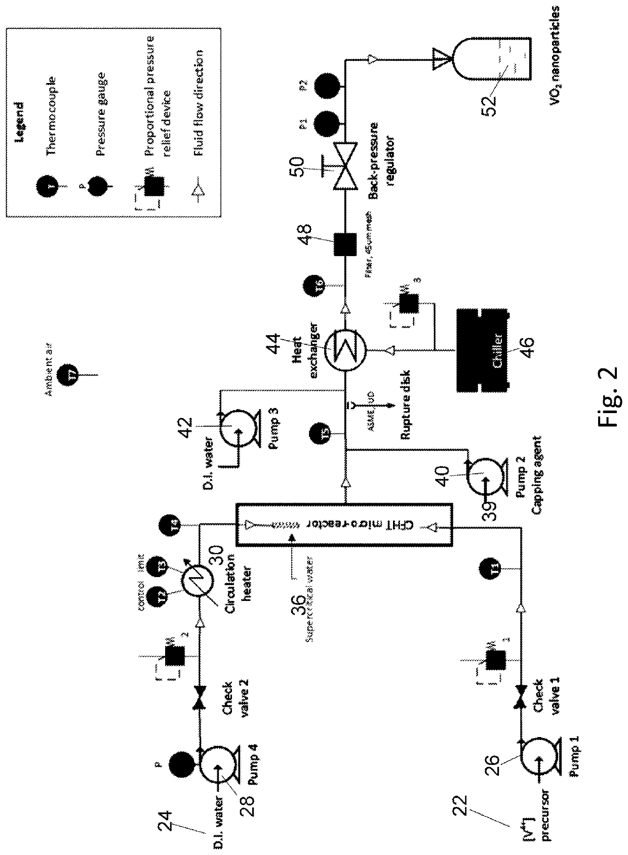
[0123]Reaction conditions for an exemplary bench top continuous flow hydrothermal core-shell particle fabrication system include a ½″ OD tubing micro-reactor, approximately 36 cm in length, with other inlet and outlet tubing of ¼″ OD. An HPLC pump is utilized to drive the precursor fluids through the mixer and micro-reactor while another diaphragm pump is utilized to pump water into the heater and micro-reactor. A stainless steel tube reactor operated under 400° C. and 240 bar may be utilized as the flow micro-reactor. A heat exchanger in fluid communication with the loop is utilized. A back pressure regulator is used to tune and maintain the system pressure. Optionally, a safety relief valve or rupture disk is provided with a maximum pressure setting of 270 bar.

[0124]The starting reagent for the experiments was a 0.0356M [V4+] precursor solution made using 1 mol vanadium pentoxide (V2O5, 1.29 g) to 3 mol oxalic acid dihydrate (C2H2O4.2H2O, 2.69 g). The solid powders were mixed with...


PUM

PropertyMeasurementUnit
size distributionaaaaaaaaaa
diameteraaaaaaaaaa
diameteraaaaaaaaaa

Abstract

The invention provides a method for continuously producing composite nanoparticles, the method comprising heating a precursor mixture with supercritical water, wherein the mixture contains a first compound capable of transitioning from a monoclinic to a tetragonal rutile crystal state; cooling the heated mixture to obtain core particles of a predetermined shape and size; encapsulating the core particle with a second precursor to create a core-shell construct; and encapsulating the construct with an organic material. Also provided is a device for continuously synthesizing composite nanoparticles, the device comprising a water supply and a precursor supply; a means for heating the water, a continuous flow hydrothermal reaction chamber adapted to receive the heated water and precursor, a means for chilling the heated water and precursor, and a capping agent supply positioned downstream of the reaction chamber. The invention also provides a nanocomposite particle comprising a core region, and a conformal organic overcoat.

Description

CONTRACTUAL ORIGIN OF THE INVENTION[0001]This invention was made with government support under Contract No. DE-AC02-06CH11357 awarded by the United States Department of Energy to UChicago Argonne, LLC, operator of Argonne National Laboratory. The government has certain rights in the invention.BACKGROUND OF THE INVENTION1. Field of the Invention[0002]This invention relates to inorganic nanoparticles and more specifically, this invention provides a nanoparticle composite and method for making a nanoparticle composite.2. Background of the Invention[0003]Inorganic nanoparticles hold promise for a myriad of applications, including thermochromics, drug delivery, communication technology, and energy conversion. However, adoption of these materials remains tepid due to a lack of efficient manufacturing processes for making same.[0004]Existing batch processes for the manufacturing of large-volume nanoparticles (i.e., between 20 nm and 30 nm in diameter) are time consuming (often taking days)...

Claims


Application Information

Patent Timeline
Patent Type & Authority Applications(United States)
IPC IPC(8): C01G31/02B01J19/00
CPCC01G31/02B82Y40/00B01J19/0093B01J19/0013C01P2004/64C01P2002/52B82Y30/00B01J2219/00166B01J2219/00033B01J2219/00051B01J2219/00162
Inventor LI, JIETRAN, MAI KIMMUEHLEISEN, RALPH T.
Owner UCHICAGO ARGONNE LLC
Why Eureka
Try Eureka