
Assay sonication apparatus and methodology

a technology of sonication apparatus and assay, which is applied in the direction of immobilised enzymes, diaphragms, rigid containers, etc., can solve the problems of affecting the accurate evaluation of a patient's condition, certain diagnostic tests are entirely unsuitable for situations, and the chemical reaction in such processes is not practicable to proceed to a meaningful completion. , to achieve the effect of facilitating concise explanation, increasing assay reaction rates, and precise tolerances

Inactive Publication Date: 2002-07-02
MESO SCALE TECH LLC
View PDF4 Cites 125 Cited by
  • Summary
  • Abstract
  • Description
  • Claims
  • Application Information

AI Technical Summary

Benefits of technology

It is an important advantage of the present invention that the structural coupling of sonication energy in apparatus according to the present invention can be precisely controlled. Such control of the structural coupling mechanism is readily implemented through precise control of the manufacturing apparatus components and the assembly of same. Each component of the structural coupling mechanism, e.g. the sonication generator, the diaphragm, etc., can be manufactured to precise tolerances. Similarly, the structural coupling mechanism is suitable for precise assembly permitting the construction of multiple apparatuses having virtually identical sonication transmission characteristics. Preferably, sonication assay cells manufactured to precise tolerances use components comprising rigid materials.
that the structural coupling of sonication energy in apparatus according to the present invention can be precisely controlled. Such control of the structural coupling mechanism is readily implemented through precise control of the manufacturing apparatus components and the assembly of same. Each component of the structural coupling mechanism, e.g. the sonication generator, the diaphragm, etc., can be manufactured to precise tolerances. Similarly, the structural coupling mechanism is suitable for precise assembly permitting the construction of multiple apparatuses having virtually identical sonication transmission characteristics. Preferably, sonication assay cells manufactured to precise tolerances use components comprising rigid materials.
The present invention is generally applicable to binding assay systems such as immunoassays, nucleic acid hybridization assays, receptor-ligand binding assays, and the like. Further assays in which the present invention is advantageously employed includes assays that involve the direct detection of an analyte, detection through a competitive binding reaction, or indirect detection, such as sandwich immunoassays, sandwich nucleic acid hybridization assays, detection of enzymatic products and detection of amplification products. Such assays may be homogeneous or heterogeneous and may or may not incorporate a wash step. The present invention is suitable for use with a variety of techniques used to detect binding events, such as ELISA, fluorescence, chemiluminescence, RIA, scintillation proximity, direct optical detection (e.g., SPR), electrochemical detection, and electrochemiluminescence. It has been found that assay systems like these are particularly responsive to sonication directly structurally coupled to the assay cell or to the assay medium. In assays where binding reactions occur in the vicinity of an electrode, sonication of the electrode itself has proven to have an especially beneficial effect in increasing assay reaction rates.
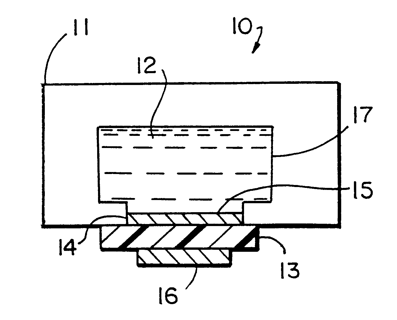
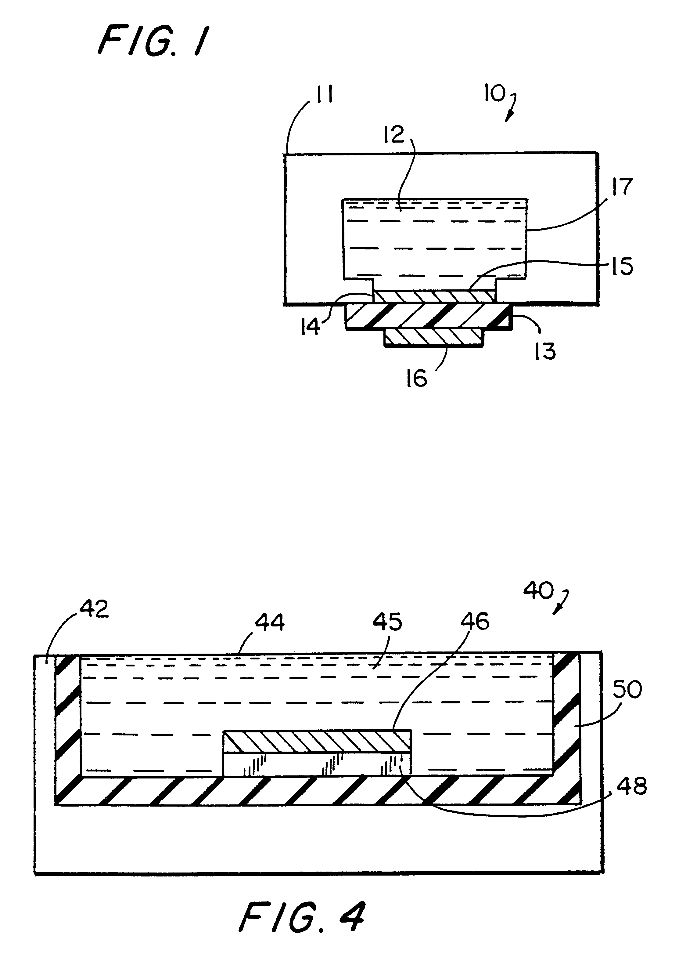
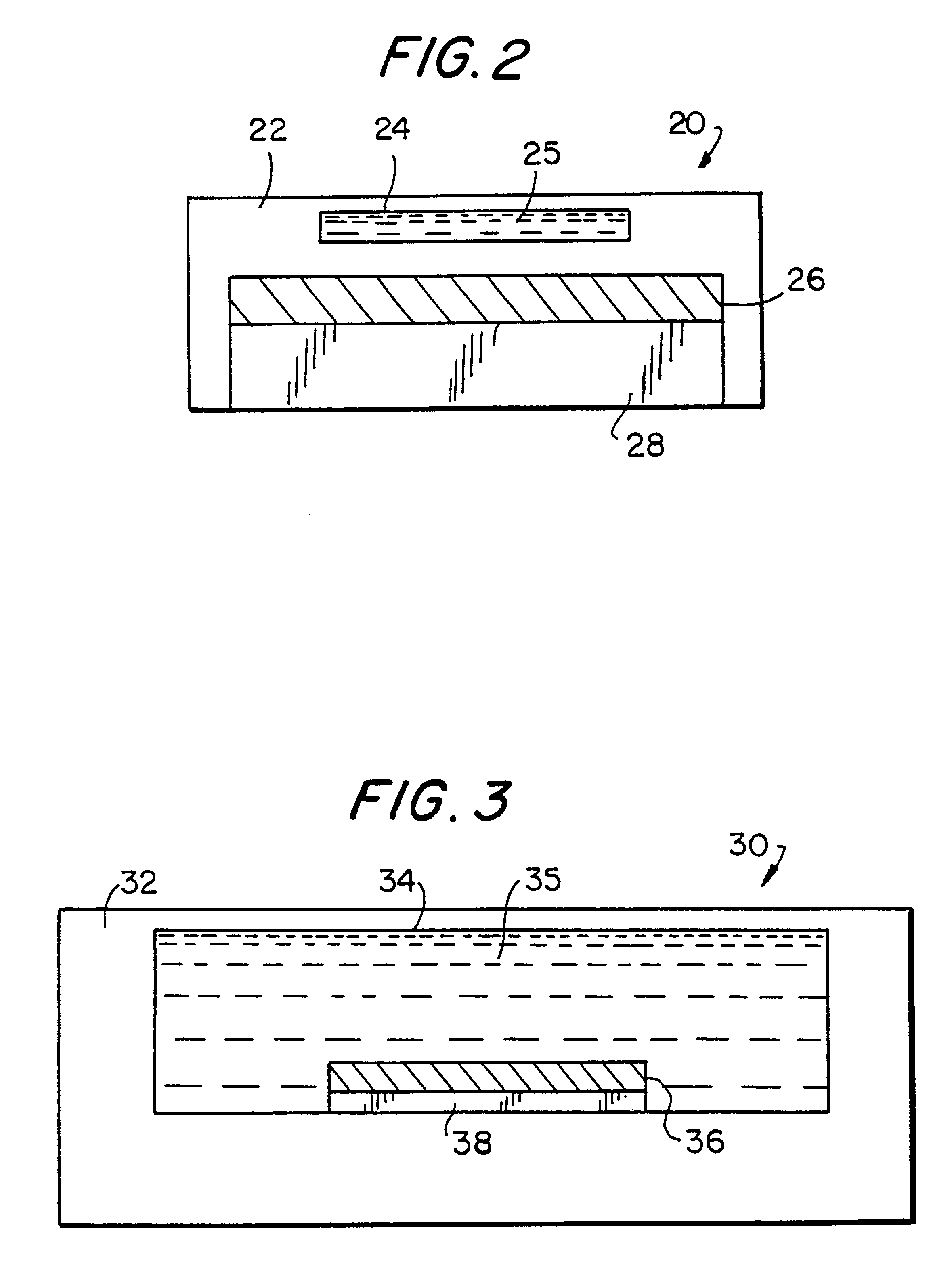
As will be understood by one of ordinary skill in the art, FIGS. 1-7 present simplified cross-sectional diagrams illustrating different assay cell designs that embody principles and useful applications of the present invention. To facilitate concise explanation but wide-ranging application, particular assay cell features and elements needed to perform specific types of assays have been omitted in some or all of the figures. The drawings, and features depicted therein, are not necessarily drawn to scale. Moreover, to further facilitate explanation of the present invention, certain features of the present invention shown in the drawings have been enlarged or reduced in size relative to other features in the same or other drawings.
In addition, description and illustration of specific electrical connections for, and mechanical couplings among, assay cell elements have been omitted to simplify the drawings. The assay cells presented may be incorporated into larger assay device systems or be available as a modular item. As an example, assay cells according to the present invention may advantageously be incorporated into the ECL systems set forth in U.S. Pat. No. 5,061,445 (Zoski et al.), U.S. Pat. No. 5,147,806 (Kamin et al.), and U.S. Pat. No. 5,247,243 (Hall et al.) as well as in copending U.S. application Ser. No. 08 / 932,110 filed on even date herewith, and PCT Application No. PCT / US97 / 16942 (WO98 / 12539) filed on even date herewith, both of which are incorporated by reference above.
In the following, each assay cell is shown containing a quantity of reagents which are labeled with the term "reagents". Such "reagents" include solid, liquid, and gaseous reagents, as well as solutions, suspensions, gels and other flowable states in which reagents may exist, combinations of any of the foregoing, and the like. Reagents may include the reagents required to perform an assay as well as a sample of unknown composition that is analyzed by an assay. Examples of suitable reagents and assay systems are found in copending U.S. application Ser. No. 08 / 932,110 filed on even date herewith, and PCT Application No. PCT / US97 / 16942 (WO98 / 12539) filed on even date herewith, both of which are incorporated by reference above.

Problems solved by technology

A significant impediment to the utilization of many diagnostic testing processes has been the impractical delay required for chemical reactions in such processes to proceed to a meaningful completion.
Such delay may make certain diagnostic tests entirely unsuitable for situations in which timely results are needed.
In an emergency room, delay in obtaining results from a diagnostic test may delay accurate evaluation of a patient's condition, to the extreme detriment of the patient.
Even under less critical circumstances, such as a routine visit to a doctor's office, an hour delay in obtaining results from a diagnostic test may hinder a doctor's diagnosis and treatment of a patient during a single consultation.
Any delay in treatment could result in harm to the patient.
At the least, an extended delay in obtaining test results may necessitate an additional follow-up consultation and office visit, thereby increasing the overall cost of treatment to the patient.
In the laboratory, the slow chemical reaction time of a diagnostic test may significantly reduce the efficiency of research efforts and burden researchers.
Further, time-consuming diagnostic testing in industrial chemical processes may dramatically increase manufacturing costs and reduce production volume.
For binding reactions that occur at a solid-phase support, the rate at which molecules in solution bind to reagents located at a solid-phase surface may be limited by the rate of mass transport of the molecules to the surface.
It has been found that diffusion rates are generally too slow to allow binding reactions to approach completion with a 30 minute period.
In addition, the presence of small convection currents in the solution, e.g., due to temperature gradients, can cause the rates of a binding reaction to vary considerably and thus be difficult to predict and control.
Such approaches commonly utilize relatively expensive and complex mechanical devices, such as solution stirrers or pumps, and, consequently, are not suited for use in an assay device that is small in size, robust, inexpensive to manufacture, and easy to use.
Such liquid-coupling is clearly inefficient and can dissipate considerable amounts of ultra sonic energy.
All of these may affect the vibration transmission characteristics of the bath.
Since small variations in structure and operational conditions will considerably affect the transmission of ultrasonic energy in a device according to Sizto et al., it can be expected that precise reproduction of particular ultrasonic bath conditions throughout the duration of a particular reaction will be extremely difficult, if not impossible, to achieve.
Consequently, it will be extremely difficult, if not impossible to achieve reproducible assay results with such a device.
Time-consuming chemical reactions sensitive to ultrasonic energy may not be reproducible at all.
In addition, the use by Sizto et al. of a liquid bath ultrasonic cleaner device presents an unnecessary risk of cross-contamination between the bath and the assay medium.
Such contamination is likely to cause erroneous assay results.
Further, an apparatus according to Sizto et al. is not particularly suited to commercial application.
As a consequence of designedly incorporating a liquid bath, the apparatus of Sizto et al. is relatively large, cumbersome and heavy and consumes considerable electrical power.
Such power is required because of the wasteful dissipation of ultrasonic energy in the bath shell, bath liquid, and assay container.
Clearly, a device according to Sizto et al. very inefficiently transmits ultrasonic energy to an assay medium in a container and from there to a binding surface.
Moreover, the use of an ultrasonication bath is an additional complicated assay step requiring skillful manipulation by a user.
As such, an ultrasonication bath is not suitable for use in an integrated, automated assay system or for use by assay technicians that are not highly skilled.
Disadvantageously, the ultrasonication bath of Sizto et al. cannot be incorporated into an assay device or assay system that is small, robust, inexpensive, easy to use.
The ultrasonication bath would also not be suitable for a disposable device.

Method used


Image

  • Assay sonication apparatus and methodology
  • Assay sonication apparatus and methodology
  • Assay sonication apparatus and methodology

Examples


example 1

Preparation of Fibril-Plastic Composites

Composite plastic materials comprising carbon fibrils in a polymer matrix were prepared by methods analogous to those described in copending U.S. application Ser. No. 08 / 932,110 filed on even date herewith, and PCT Application No. PCT / US97 / 16942 (WO98 / 12539) filed on even date herewith, both of which are incorporated by reference above. To give a better understanding of the following examples, a brief description of the steps for preparing the composites used in the examples is provided. Carbon fibrils (Hyperion Catalysis) were compounded with poly(ethylene-co-vinyl acetate) (EVA) and the resulting composite material was extruded into sheets. The sheets were oxidized with chromic acid to expose carbon fibrils near the surface and to introduce carboxylic acid groups. Protein was immobilized on the composite by activation of the carboxylic acid groups with ethyl-dimethylpropyl-carbodiimide (EDC) in the presence of N-hydroxysuccinimide (NHS) foll...

example 2

Increasing the Rates of Binding Reactions at a Solid-Phase Support with Sonication: Use of a Low-Power Piezoelectric Buzzer

Streptavidin was immobilized onto chromic acid-oxidized EVA-fibril composite as described in Example 1. A 5 / 16 inch diameter disc cut from this material was placed in the well formed by placing a gasket on a low-power low-frequency acoustic piezoelectric transducer. Treatment of the disc with a solution containing a biotin-labeled .alpha.-Fetoprotein (anti-AFP) antibody (Boeringer-Mannheim, 50 uL, 41 nM) led to immobilization of the antibody. The binding reaction was essentially complete in 3 minutes upon sonication by the piezoelectric transducer. The extent of the reaction was determined using a biotin- and TAG1-labeled antibody and measuring bound antibody by ECL. The same reaction took more than 20 minutes when mass-transport occurred through diffusion alone that is, without sonication.

The antibody-coated composite was washed with 50 mM phosphate, pH 7.5. To...

example 3

Increasing the Rates of Binding Reactions at a Solid-Phase Support with Sonication: Use of an ECL Cell Instrument with an Integrated Piezoelectric Sonication Device

EVA-fibril composite was treated with a water-saturated argon plasma and coated with an anti-AFP antibody (Boeringer-Mannheim) as described in Example 1. A 10.times.15 mm rectangle of the composite was placed in an ECL cell (see FIG. 6).

The sample (10 uL) and a solution containing a TAG1-labeled anti-AFP antibody (Boeringer-Mannheim, 50 uL, 12 ug / mL) were combined and introduced into the cell. The binding reaction was allowed to proceed for 3 minutes during which time a piezoelectric transducer (sonication generator) was driven at its resonance frequency (47 KHz) at a power of approximately 2.5 W. The transducer was turned off, the cell was flushed with ORIGEN Assay Buffer (IGEN, International), and the voltage at the composite was ramped from 0 to -0.8 to 1.2 V (vs. Ag / AgCl) at a rate of 0.1 V / s. The difference between t...


PUM

PropertyMeasurementUnit
poweraaaaaaaaaa
frequencyaaaaaaaaaa
frequencyaaaaaaaaaa

Abstract

An assay apparatus includes a cell with a working electrode and a sonicating device structurally coupled to the cell for sonication the contents of the cell.

Description

REFERENCE TO PUBLICATIONS AND CORRESPONDING APPLICATIONSThe following published PCT Applications are hereby incorporated in their entirety by reference: U.S. No. 92 / 00982 (WO92 / 14138); U.S. No. 92 / 00992 (WO 92 / 14139); and U.S. No. 96 / 03190 (WO96 / 28538).The following commonly owned and copending U.S. and PCT Applications, filed on even date herewith are incorporated in their entirety by reference: U.S. patent application Ser. No. 08 / 932,110 filed Sep. 17, 1997 entitled MULTI-ARRAY, MULTI-SPECIFIC ELECTROCHEMILUMINESCENCE TESTING and PCT Application No. PCT / US97 / 16942 filed Sep. 17, 1997 entitled MULTI-ARRAY, MULTI-SPECIFIC ELECTROCHEMILUMINESCENCE TESTING (WO98 / 12539).Diagnostic tests upon liquid samples and diagnostic tests utilizing liquids are in widespread use in medical technology, environmental monitoring devices, and commercial applications. A significant impediment to the utilization of many diagnostic testing processes has been the impractical delay required for chemical rea...

Claims


Application Information

Patent Timeline
Patent Type & Authority Patents(United States)
IPC IPC(8): C12M1/33C12M3/08G01N33/543G01N33/53
CPCG01N33/5302G01N33/5438Y10S435/808Y10S436/805G01N21/76
Inventor WOHLSTADTER, JACOB N.WILBUR, JAMESSIGAL, GEORGEMARTIN, MARKFISCHER, ALANHELMS, LARRY R.DARVARI, RAMIN
Owner MESO SCALE TECH LLC
Learn More