Methods of isolating blood components using a microcentrifuge and uses thereof

a technology of microcentrifuge and isolating blood components, which is applied in the direction of centrifuges, instruments, prostheses, etc., can solve the problems of large extracorporeal volume (i.e., the amount of blood that is out of the donor at any given time during the process), difficult or impossible to use discontinuous systems on people, and difficult to control the hematocrit of the final produ

Inactive Publication Date: 2005-05-10
ARTERIOCYTE MEDICAL SYST
View PDF14 Cites 67 Cited by
  • Summary
  • Abstract
  • Description
  • Claims
  • Application Information

AI Technical Summary

Benefits of technology

[0062]This invention further provides a centrifugal liquid processing system that may be automated.
[0063]T...

Problems solved by technology

Discontinuous-flow systems have the advantage that the rotors are relatively small in diameter but have the disadvantage that the extracorporeal volume (i.e., the amount of blood that is out of the donor at any given time during the process) is large.
This, in turn, makes it difficult or impossible to use discontinuous systems on people whose size and weight will not permit the drawing of the amount of blood required to fill the rotor.
Because the bowls in these systems are rigid and have a fixed volume, however, it is difficult to control the hematocrit of the final product, particularly if the amount of blood salvaged is insufficient to fill the bowl with red blood cells.
The McMannis, et al., system takes up a fairly large amount of space, and its flexible pancake-shaped rotor is awkward to handle.
The McMannis, et al., system does not permit the fluid medium to flow into and out of the processing bag at the same time, nor does it permit fluid medium to be pulled out of the processing bag by suction.
Although continuous-flow systems have the advantage that the amount of blood that must be outside the donor or patient can be relatively small, they have the disadvantage that the diameter of the rotor is large.
These systems are, as a consequence, large.
Furthermore, they are complicated to set up and use.
One drawback present in the above-described continuous-flow systems has been their use of a rotating seal or coupling element between that portion of the system carried by the centrifuge rotor and that portion of the system that remains stationary.
While such rotating seals have provided generally satisfactory performance, they have been expensive to manufacture and have unnecessarily added to the cost of the flow systems.
Furthermore, such rotating seals introduce an additional component into the system which if defective can cause contamination of the blood being processed.
The continuous-flow systems described above are large and expensive units that are not intended to be portable.
Further, they are also an order of magnitude more expensive than a standard, multi-container blood collection set.
Nevertheless, the whole process remains laborious and requires the separation to occur within a certain time frame to guarantee the quality of the blood components.
This complicates the logistics, especially considering that most blood donations are performed in decentralized locatio...

Method used


Image

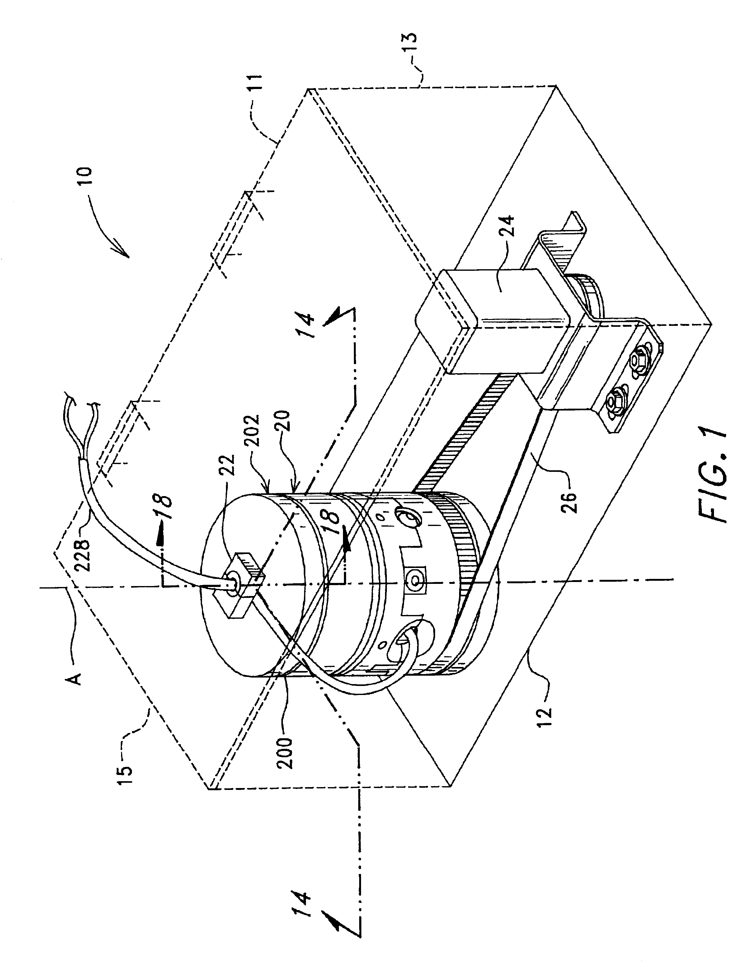
  • Methods of isolating blood components using a microcentrifuge and uses thereof
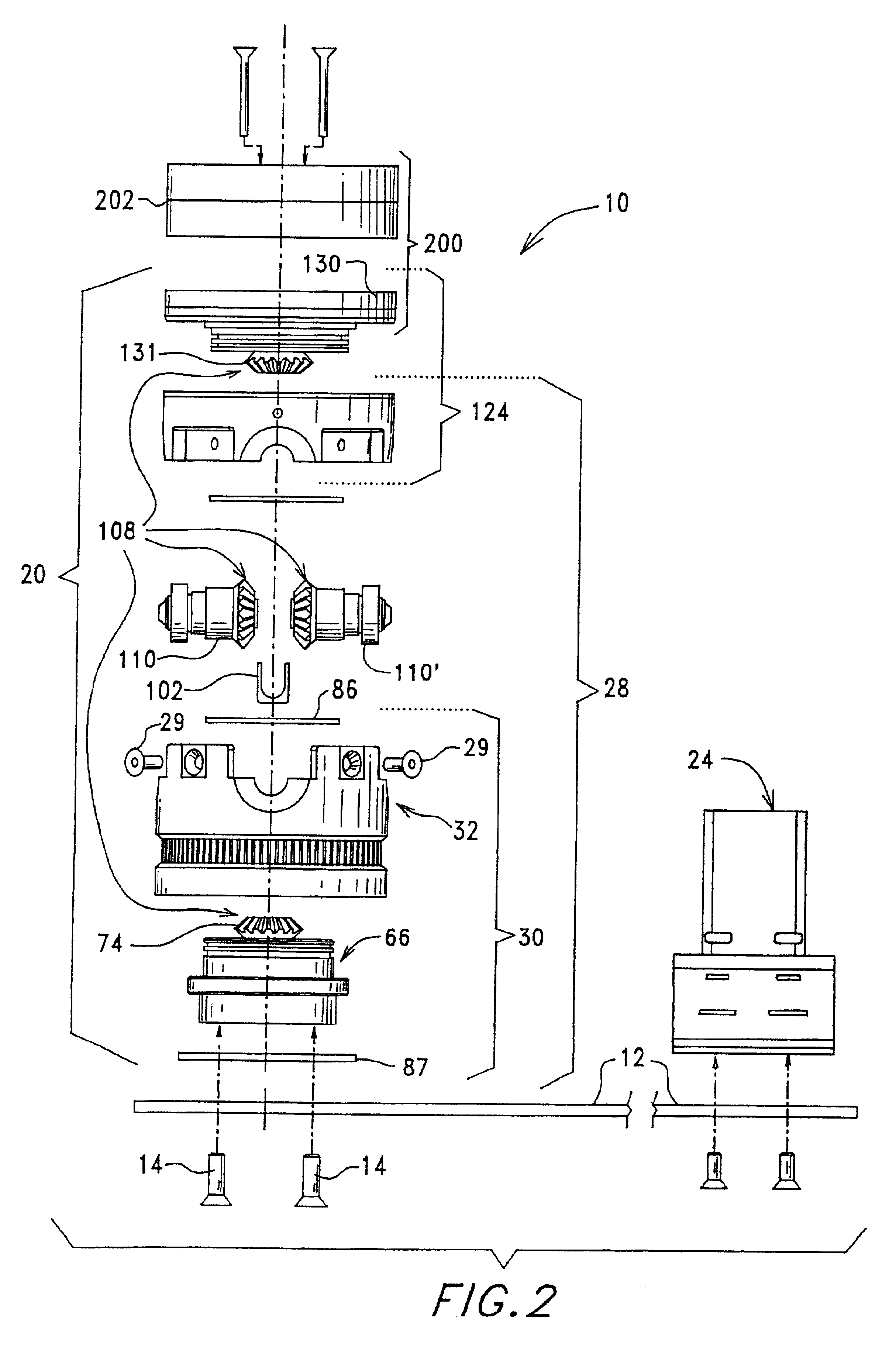
  • Methods of isolating blood components using a microcentrifuge and uses thereof
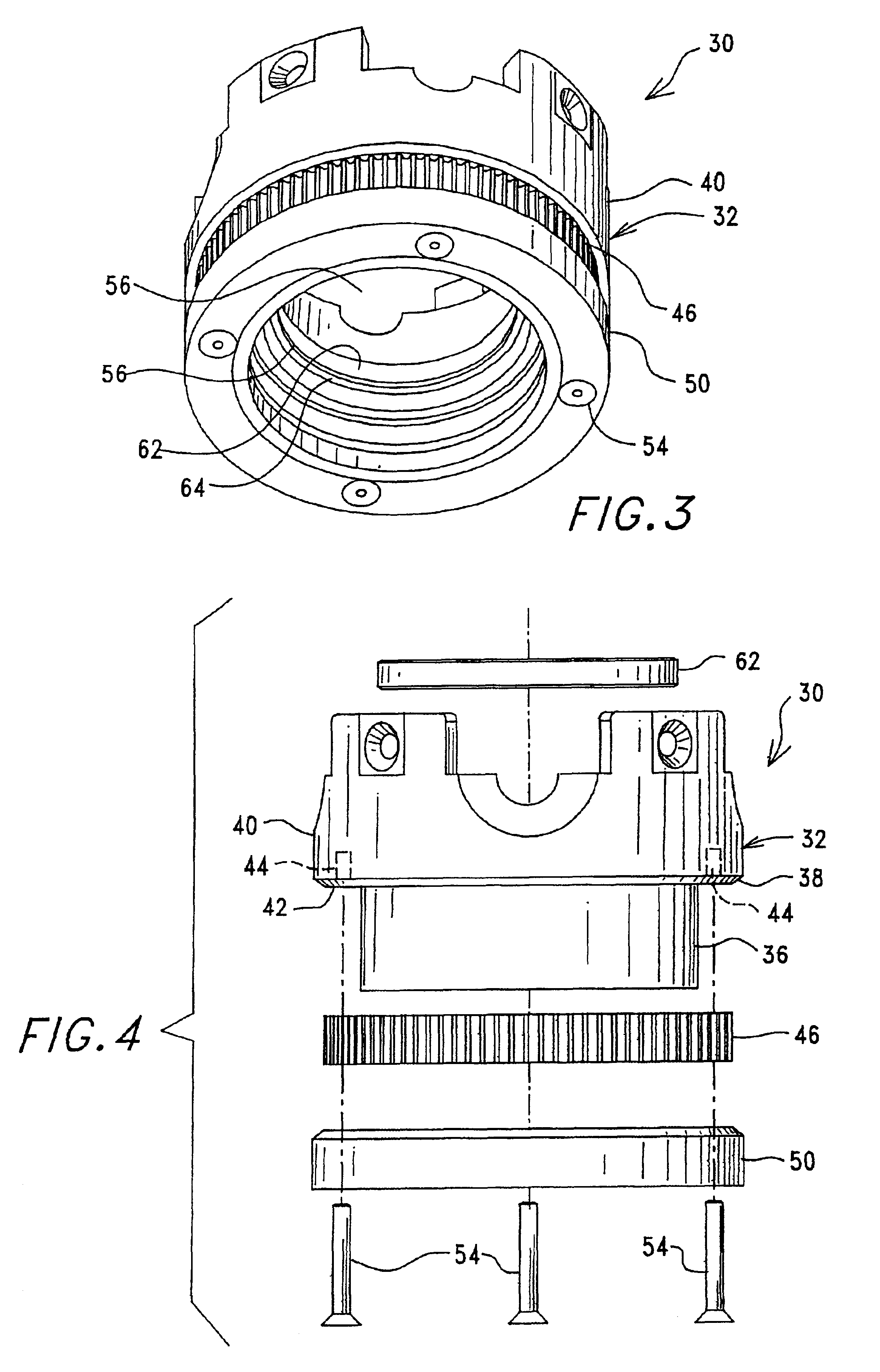
  • Methods of isolating blood components using a microcentrifuge and uses thereof

Examples


example 1

Transfecting Buffy Coat with an LMP-1 Adenovirus Construct

[0303]The buffy coats isolated according to the methods of this invention may be used for genetic transformations. For example, a sample of whole blood was separated using a centrifuge device of this invention to isolate buffy coat. The isolated cells were washed and counted, and then transfected with the LMP-1 Adenovirus as disclosed in a copending U.S. patent application to Medtronic, Inc., which is specifically incorporated herein by reference. The results of one such experiment are shown in Table 1. In this experiment, the surgery date was Nov. 28, 2000 and the sacrificing date was Jan. 2, 2001.

[0304]

TABLE 1RESULTS: RABBIT EXPERIMENT #36GROSSANIMALPALPATIONFUSIONRADIOGRAPHSCT SCANNo.LeftRightSTATUSLeftRightLeftRightOBSERVATIONS172420 μg / 4M2 or 3+2 or 3+F4+4+pHIShLMPtGene Box17252+2+F4+4+1726R = 6.0 / 4M3+3+F4+4+AdenovirusGene Box17273+2+F4+3+Right side infectionCODE SYSTEM: B = bone NB = no bone F = fused NF = no fusion FT ...

example 2

Preparation of Bioadhesive Sealant Composition Using Platelet Rich Plasma and Serum

[0306]6 cc's of platelet rich plasma are drawn into receiving chamber 961 and 3 cc's of either platelet rich plasma (PRP) or platelet poor plasma (PPP) are drawn into receiving chamber 957 which further contains 0.33 cc's of 10% calcium chloride and glass wool. Clotting of the contents will occur in two to eight minutes in receiving chamber 957. The clot is then squeezed through optional filter 958, and the serum produced therefrom is added to the platelet rich plasma contained in receiving chamber 961 by either mixing or spraying the two components. The platelet rich plasma and the serum will gel within approximately three minutes.

[0307]The application of the gel using the syringe-type devices 902 as described above maybe less than desirable for may applications. Consequently, in an alternate embodiment the inactive blood component and thrombin can be mixed and / or injected into a mold having a desire...


PUM

PropertyMeasurementUnit
Fractionaaaaaaaaaa
Shapeaaaaaaaaaa

Abstract

Methods and apparatuses for the separation a predetermined cellular component from a bodily fluid or tissue by centrifugation are provided. More specifically, this invention provides a method for the separation and isolation of one or more components, such as stem cells, buffy coat, bone marrow cells, erythrocytes, leukocytes, thrombocytes, serum, fluorescently labeled cells, and magnetically labeled cells, from whole blood, bone marrow, buffy coat, fat tissue, muscle tissue, and nerve tissue by centrifugation, wherein the components are isolated while the centrifuge is rotating.

Description

RELATED APPLICATIONS[0001]This application claims priority to U.S. Provisional Application Ser. No. 60 / 283,141, filed Apr. 9, 2001, and entitled “Methods of Isolating Blood Components Using a Microcentrifuge and Uses Thereof.”BACKGROUND OF THE INVENTION[0002]1. Field of the Invention[0003]This invention relates to novel methods, devices and apparatuses for the centrifugal separation of a liquid into its components of varying specific gravities, and is more particularly directed toward a blood separation device useful, for example, in the separation of blood components for use in various therapeutic regimens.[0004]2. Description of the State of Art[0005]Centrifugation utilizes the principle that particles suspended in solution will assume a particular radial position within the centrifuge rotor based upon their respective densities and will therefore separate when the centrifuge is rotated at an appropriate angular velocity for an appropriate period of time. Centrifugal liquid proces...

Claims


Application Information

Patent Timeline
IPC IPC(8): A61K35/14C12N15/09A61K35/12A61K35/15A61K35/19A61K48/00A61L27/00A61M1/02A61M1/36A61P19/10B04B5/00B04B5/04B04B11/02C12N5/08C12N5/10
CPCA61K35/19A61M1/3693B04B5/0428A61M1/3696A61K35/15A61M1/3616A61M1/3618B04B5/0442A61M2202/045A61M2202/10B04B2005/045A61P19/10A61M1/3623
Inventor DOLECEK, VICTOR D.MARX, JEFFERY C.MCKAY, WILLIAM F.
Owner ARTERIOCYTE MEDICAL SYST
Why Eureka
Try Eureka