
Chalcogenide glass for low viscosity extrusion and injection molding

a technology of chalcogenide glass and low viscosity, applied in the field of optical components, can solve the problems of large-scale manufacturing, unsuitable methods, and high cost of methods, and the vast majority of conventional machining processes for manufacturing optical components

Active Publication Date: 2006-10-03
CORNING INC
View PDF11 Cites 83 Cited by
  • Summary
  • Abstract
  • Description
  • Claims
  • Application Information

AI Technical Summary

Benefits of technology

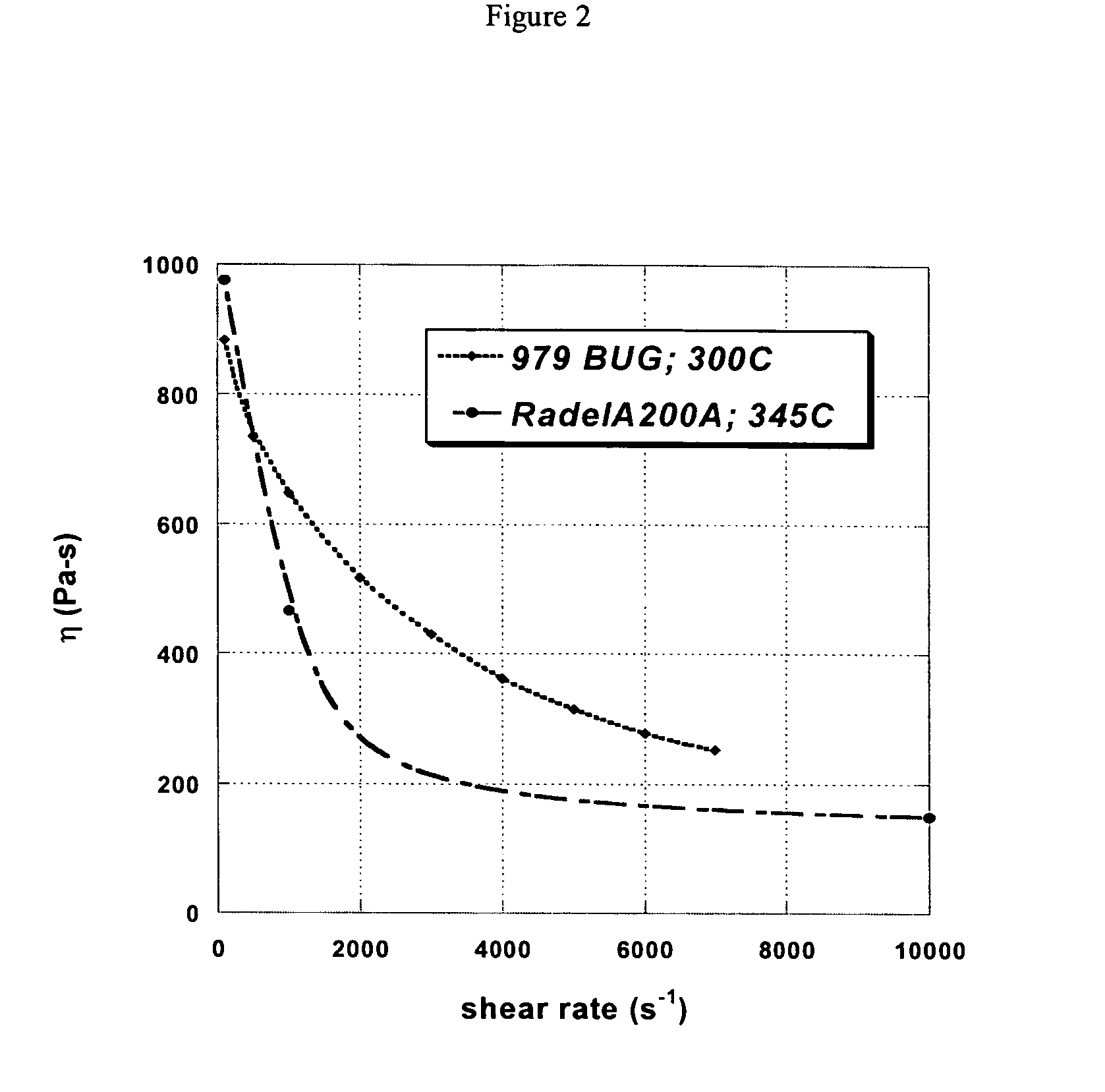
[0015]The invention is further directed to chalcogenide glass compositions that can be used in extrusion and injection molding processes. In particular, the glasses of the invention can be used in continuous screw-extrusion processes, as well as screw injection molding processes, traditionally used for low-cost manufacturing of plastic articles.

Problems solved by technology

However, a great majority of conventional machining processes for manufacturing optical components are unsuited for producing very small features.
However, these methods are not suitable for large-scale manufacturing.
Moreover, not only are such methods expensive, but they can produce only a limited range of feature types.
Etching processes are particularly worrisome because they can create rough surfaces.
As a result, a smooth concave or convex profile, or true prismatic profiles, cannot be readily achieved using either of the two foregoing techniques.
Unfortunately for many telecommunication applications, plastic materials are not ideal since they suffer from numerous shortcomings.
For example, plastic materials have limited mechanical properties; are often not sufficiently robust to withstand, over time, environmental degradation; they exhibit large coefficients of thermal expansion (which can result in changes in volume and index of refraction); and it has been found that plastic optical devices often cannot withstand long exposure to humidity or high temperatures—all of which thereby limit the temperature range over which plastic optical devices may be useful.
As a result, one cannot use plastic materials to form a lens or other optical device in the IR range where the plastic absorbs.
Further, plastics cannot transmit high-power light due to internal heating of the material that will cause a plastic component's surface features to degrade and its index of refraction to change—both of which are unacceptable in an optical context.
In addition, since plastic materials for optical applications are available in only a limited range of dispersion and refractive indices, plastics can provide only a restricted transmission range.
As a result, the usefulness of plastic materials, even within the restricted telecommunications bandwidth, is limited by the tendency to accumulate internal stresses; a condition that results in distortion of transmitted light during use.
Many plastics also scratch easily and are prone to yellowing or developing haze and birefringence; and the application of abrasive-resistant and anti-reflective coatings still has not fully solved these flaws for plastic materials.
Finally, many chemical and environmental agents degrade plastics, which make them difficult to clean effectively.
However, the requirements of the molding processes that use glass are more stringent than those for plastics.
The surface quality and finish of the body at this stage of production, however, are not adequate for image forming optics.
Both of these methods have their limitations.
Grinding and polishing are restricted to producing relatively simple shapes, for example, flats, spheres, and parabolas.
Other shapes and general aspheric surfaces are difficult to grind and complicated to polish.
On the other hand, conventional techniques for hot pressing of glass do not provide the exacting surface features and qualities that are required for clear image forming or transmission applications.
The presence of chill wrinkles in the surface and surface features are unacceptable defects.
Glass molding has also traditionally presented a number of other problems.
However, at such relatively high temperatures glass becomes highly chemically reactive.
However, in many cases such materials cannot attain sufficient surface smoothness for making satisfactory optical quality surface finishes.
Metal molds can deform and re-crystallize at high temperatures, both of which can adversely affect the surface and optical qualities of the article being molded.
This means additional costs to repair and maintain the molds, and higher defect rates in the product.
Second, also due to the reactivity of the glass at high temperatures, the molding often must be carried out an inert atmosphere which complicates the process and increases costs.
Third, the potential for air or gas bubbles to be entrapped in the molded articles is another drawback of high-temperature molding.
Gas bubbles trapped within glass articles degrade the optical properties of the articles.
The bubbles distort images and generally disrupt optical transmission.
Fourth, even at high temperatures, hot-glass molding cannot create intricate, high-frequency, submillimeter microstructures such as those required for diffraction gratings.

Method used


Image

  • Chalcogenide glass for low viscosity extrusion and injection molding
  • Chalcogenide glass for low viscosity extrusion and injection molding
  • Chalcogenide glass for low viscosity extrusion and injection molding

Examples


example 1

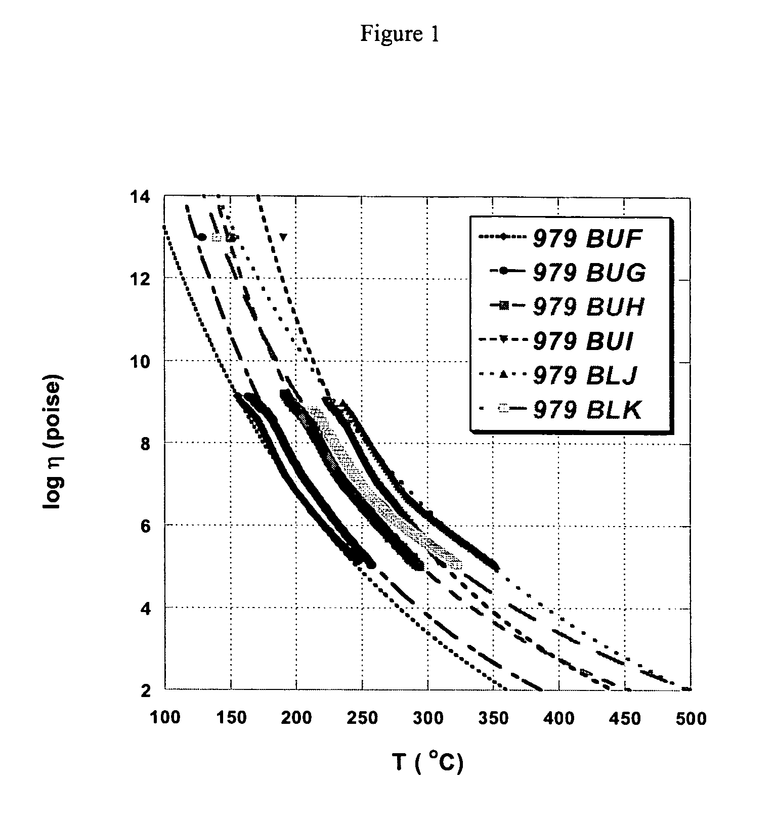
[0042]By way of illustration not to be construed as limiting the invention, the chalcogenide glass 979 BUG was prepared and extruded in the following manner which is representative of the process of the invention. The equipment used in the following process is all commercially available.

[0043]A mixture, in atomic percent, of 1.6% Ge, 28.4% As and 70% Se was mixed together in an amount sufficient to prepare a 500 gram glass boule and placed in a quartz ampoule that was evacuated (to 10−3 mm Hg or less) and sealed. The ampoule was heated to a temperature of approximately 800° C. for a time in the range of 30-36 hours, slow cooled to 500° C., and then rapidly cooled (quenched) by immersing the ampoule in a 4000 ml beaker of room temperature water until the chalcogenide glass delaminated from the ampoule wall. At this point the ampoule was placed in an annealing furnace at an approximate temperature of 125° C. and held at this temperature for 0.25 to 2 hours. The furnace power was then ...

example 2

[0049]A two-cavity, double convex lens (25 mm diameter by 8 mm thick) mold was used to injection mold the 979BUG glass composition on an Arburg 370 CS 600–100 molding machine (Arburg, Inc., Newington, Conn.), which had a 30 mm diameter injection unit with a 2:1 compression-ratio screw. A thin layer of boron nitride, from water slurry, was applied to all surfaces of the screw, nozzle, sprue bushing, runner, gates and cavity to prevent adhesion of the glass. Crushed glass was sieved to a particle size range of approximately 0.5–2.0 mm, and placed in a standard hopper for flood feeding. Parts were molded at the following process conditions given in Table 2.

[0050]

TABLE 2PositionTemp., ° C.:Other ConditionsFeed Throat52Clamp Force400kNZone 1293Shot Size15.00ccmZone 2299Switchover Point7.9ccmZone 3305Injection Speed20ccm / sec.Zone 4305Switchover Pressure670barNozzle295Hold Pressure900barMold235Hold Time5.0sec.Circumfer. Screw4.0m / min.SpeedBack Pressure30barCooling Time45sec.Total Machine T...


PUM

PropertyMeasurementUnit
Temperatureaaaaaaaaaa
Fractionaaaaaaaaaa

Abstract

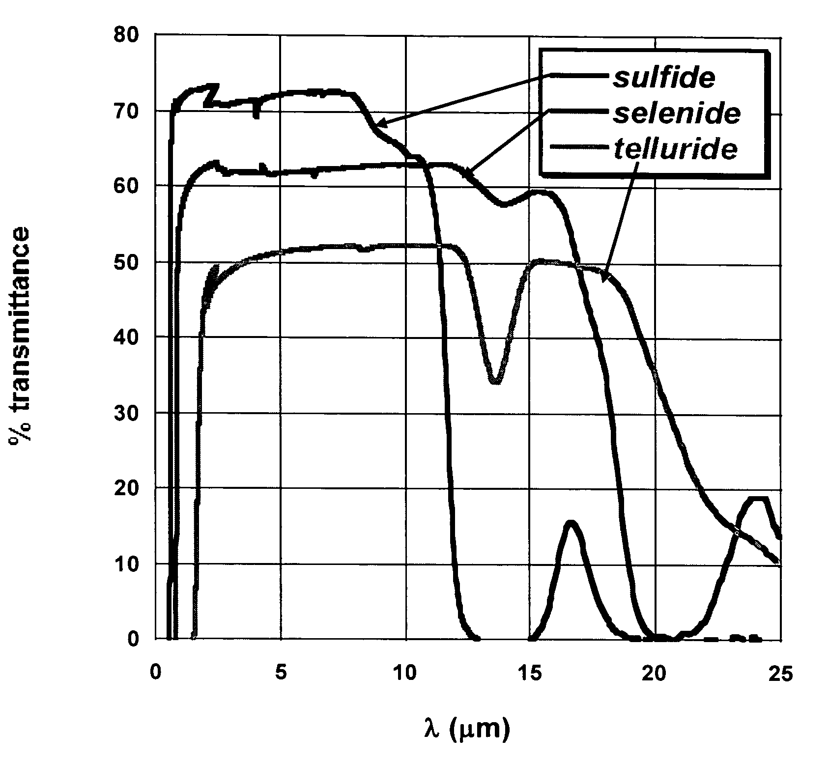
The invention is directed to chalcogenide glasses suitable for use in plastics forming processes. The glasses have the general formula YZ, where Y is Ge, As, Sb or a mixture of two or more of the same; Z is S, Se, Te, or a mixture of two or more of the same; and Y and Z are present in amounts (in atomic / element percent) in the range of Y=15–70% and Z=30–85%. The chalcogenide glasses of the invention have a 10,000 poise temperature of 400° C. and are resistant to crystallization when processed at high shear rates at their 10,000 poise temperature. The glasses can be used to make, among other items, molded telecommunication elements, lenses and infrared sensing devices.

Description

FIELD OF THE INVENTION[0001]The present invention relates to optical components and their manufacture using non-oxide glass materials. In particular, the invention relates to chalcogenide glasses that have low glass-transition temperatures (Tg), and can be processed by conventional plastics forming techniques such as injection molding, extrusion, embossing, thermoforming, blow-molding, rotational molding, and similar methods known in the art.BACKGROUND OF THE INVENTION[0002]Optical elements have had various uses in many diverse technologies, including sensors, image projectors, displays (e.g., liquid crystal displays (LCDs), plasma display, and electro-luminescence display), as well as opto-electronic devices for telecommunications. As the telecommunications industry itself develops, the need to develop precision optical elements that incorporate microstructures increases. In telecommunication devices, optical elements may be used, for example, in fiber and laser couplers, optical s...

Claims


Application Information

Patent Timeline
IPC IPC(8): G02B6/00G02B6/02
CPCC03C3/321C03C13/043G02B1/00G02B6/02
Inventor AITKEN, BRUCE GARDINERCURRIE, STEPHEN CHARLESMONAHAN, BETH COSTELLOWU, LUNG-MINGCOONAN, EVERETT WILLIAM
Owner CORNING INC
Learn More