
Electrolyte solution for secondary battery and secondary battery using the same

Active Publication Date: 2007-01-16
NEC CORP
View PDF16 Cites 36 Cited by
  • Summary
  • Abstract
  • Description
  • Claims
  • Application Information

AI Technical Summary

Benefits of technology

[0021]The electrolyte solution for the secondary battery according to the present invention includes cyclic sulfonic ester including at least two sulfonyl groups. Such cyclic sulfonic ester contributes the formation of the passivation coating at an electrode interface of the battery, resulting that the decomposition of solvent molecules is prohibited. Also, when the cathode is made of an oxide including manganese, the configuration of the present invention provides preventing the elution of the manganese and further preventing the adhesion of the eluted manganese onto the anode. Thus, the electrolyte solution for the secondary battery according to the present invention can be employed for the secondary battery to form the coating on the anode, providing the advantageous effects such as the effect of decreasing the influence against the elution of the manganese or the like, and therefore, the cycle properties of the secondary battery according to the present invention can be improved by the advantageous effects. In addition, the increase of the resistance of the secondary battery can also be prohibited.
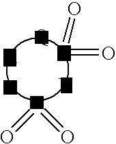
[0022]In the electrolyte solution for the secondary battery according to the present invention the aforementioned cyclic sulfonic ester may be a compound represented by a general formula (1) described below:
[0023](where: Q is oxygen atom, methylene group or single bond; A is substituted or non-substituted alkylene group containing 1 to 5 carbons, carbonyl group, sulfinyl group, substituted or non-substituted fluoroalkylene group containing 1 to 6 carbons or divalent group containing 2 to 6 carbons being bonded to alkylene unit or fluoroalkylene unit via ether bond; and B is substituted or non-substituted alkylene group, substituted or non-substituted fluoroalkylene group or oxygen atom.)
[0024]The electrolyte solution for the secondary battery according to the present invention contains the compound shown in the general formula (1). The compound shown in the general formula (1) contributes the formation of the passivation coating at an electrode interface of the battery, resulting that the decomposition of solvent molecules is prohibited. Also, when the cathode is made of an oxide including manganese, the configuration of the present invention provides preventing the elution of the manganese and further preventing the adhesion of the eluted manganese onto the anode. Thus, the electrolyte solution for the secondary battery according to the present invention can be employed for the secondary battery to form the coating on the anode, providing the advantageous effects such as the effect of decreasing the influence against the elution of the manganese or the like, and therefore, the cycle life of the secondary battery according to the present invention can be improved by the advantageous effects, and the increase of the resistance of the secondary battery can also be prohibited.
[0025]In the above-shown general formula (1), when Q is single bond, the chemical structure thereof is that carbon atom contained in A and S (sulfur) constitute C—S single bond.
[0026]Further, in the above-shown general formula (1), the number of carbon atoms indicates the number of carbons constituting the loop and not including the number of carbons disposed in the branches. When A is substituted or non-substituted fluoroalkylene group containing 1 to 6 carbons, A may comprises methylene unit and fluoromethylene unit, or may only fluoromethylene unit. When A is bonded to alkylene unit or fluoroalkylene unit via ether bond, alkylene units may be mutually bonded, fluoroalkylene unit may be mutually bonded, or alkylene unit and fluoroalkylene unit may be bonded.

Problems solved by technology

When the metallic lithium anode or the lithium alloy anode is employed, the problems of lower efficiency of electrical charging and discharging or the problems of lower safety due to the formation of the dendrite crystal (tree branch-shaped crystal) must be solved.
However, since the lithium fluoride film is obtainable via the reaction between the anode interface and the solution, it is difficult to obtain uniform lithium fluoride film, as the surface film is easily contaminated with the reaction byproducts generated during the reaction.
Further, when the surface film of native lithium hydroxide or native lithium oxide is not uniformly formed, the surface film may partially include bare lithium surfaces.
In such case, uniform thin film of lithium fluoride is not obtainable, and further serious safety problems of possibly reacting the bare lithium surface with water or hydrogen fluoride may be caused.
In addition, when the reaction is insufficient and not completed, unwanted other products than fluorides may remain in the surface film, thereby possibly causing harmful effects such as deterioration of ion conductivity.
In addition, in the method of forming the fluoride layer by employing the chemical reaction occurred on the interface, the availability of fluorides and electrolyte solutions is strictly limited, thereby making it difficult to form the stable surface film with higher process yield.
However, when a surface film of other material, in particular a surface film of a plurality of chemical compounds, already exists on the metallic lithium surface before forming the surface film of lithium fluoride thereon, reaction tends to proceeds non-uniformly, so that it is difficult to form a uniform film of lithium fluoride.
In this reason, it is difficult to obtain a lithium secondary battery having sufficient cycle properties.
This technique cannot sufficiently prevent the formation of the dendrite deposition, since the lithium sheet used in this technique is manufactured via flat rolling process, in which the lithium sheet may be exposed to the air atmosphere so that the native surface coatings derived by moisture and the like may easily be formed partially on the surface of the lithium sheet during the process, thereby non-uniformly distributing the active areas across the surface of the sheet, and being difficult to form the targeted stable surface film.
This method is effective in improving the cycle life in a certain level, but not sufficient.
In addition, this method requires relatively expensive lithium imide salt such as LiN(C2F5SO2)2.
Other Lithium imide salt cannot be employed for this method, since the complex of transition metal and imide anion is not formed when adding the complex of other lithium salt (e.g., typically LiPF6) transition metal and CF3SO3−F3S ion, and thus the cycle properties can not be improved.
Further, the use of lithium imide salts as the electrolyte solution provides higher resistance of the electrolyte solution than the use of LiPF6 and the like, thereby causing a problem of increasing the internal resistance of the battery.
However, in this method, aluminum reacts with a slight amount of water, thereby causing a problem of rapidly decreasing the electrical capacity of the battery when cycles are repeated.
However, cracks are generated in the solid electrolyte due to the stress variation when lithium ion is inserted and desorbed, and the cracks lead to the deterioration of the properties thereof.
Further, the quality of the solid electrolyte is not uniform due to the crystalline defects contained therein, and the non-uniformity of the quality leads to non-uniform reaction across the surface of the anode, thereby deteriorating the cycle life.
However, this method does not provide sufficient coating effect, such that the electrical charge generated by decomposition of solvent molecule or anion appears as an irreversible electrical capacity component, thereby decreasing the initial charge-discharge efficiency.
Further, the resistance of thus formed coating is high, and in particular, the rate of the increase of the resistance with time or during storing in high temperature is considerably large.
As described above, the techniques disclosed in the prior art documents cannot provide sufficient improvement in the battery properties, and in particular, cannot provide sufficient effect on improving the charge-discharge efficiency and on preventing the increase of the resistance during storing.
Thus, the following problems arise in the prior art.
However, there is no established method of continuously controlling the characteristics of the surface film in longer term.
However, in the repeated operation, the surface film becomes degraded and the function of the protective film is impaired.
The generation of the internal stress causes the breakage in a part of the surface film of, in particular lithium halides, thereby deteriorating the function of inhibiting dendrite growth.
Further, in relation to the carbon materials such as graphite, the surface coating cannot provide sufficient coating effect, the electrical charge generated by the decomposition of solvent molecule or anion appears as an irreversible electrical capacity component, thereby decreasing the initial charge-discharge efficiency.
However, there is no established method of continuously controlling the characteristics of the surface film in longer term, and it has been desired to develop an electrolyte solution, which is stable with the material of the anode and contributes to the sufficient charge-discharge efficiency.

Method used


Image

  • Electrolyte solution for secondary battery and secondary battery using the same
  • Electrolyte solution for secondary battery and secondary battery using the same
  • Electrolyte solution for secondary battery and secondary battery using the same

Examples


example 1

(Preparation of the Battery)

[0085]Preparation of the battery according to the present example will be described. An aluminum foil having a thickness of 20 μm was employed for a cathode active material, and LiMn2O4 was employed for an anode active material. A copper foil having a thickness of 10 μm was employed for an anode electric collector, and metallic lithium as an anode active material was deposited on the copper foil to a thickness of 20 μm to form an anode. A mixed solvent of EC and DEC (in a volumetric ratio of 30:70) was employed for an electrolyte solution, and 1 molL−1 of LiN(C2F5SO2)2 (hereinafter abbreviated to as LiBETI) as a support electrolyte was dissolved into the solvent, and further the compound No. 1 shown in the above TABLE-1 was added thereto to achieve a concentration of the compound No. 1 of 1% wt. Then, the anode and the cathode were laminated, between which a separator comprising polyethylene was disposed, to form a laminate packaging secondary battery.

(Ch...

examples 2 – 4

Examples 2–4

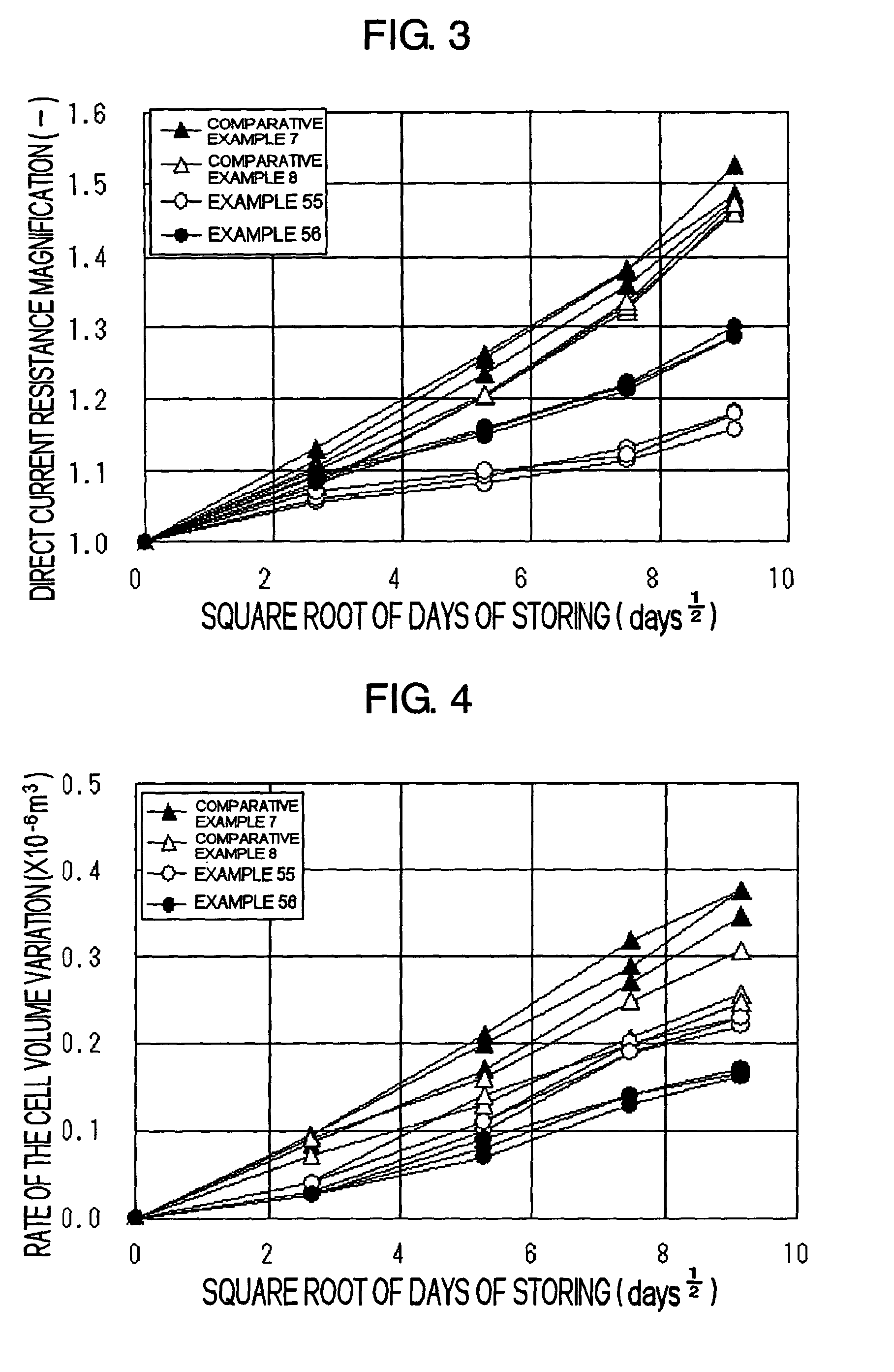
[0087]Secondary batteries were prepared in the same manner as in Example 1 except that the compound No. 1 was replaced with the compound shown in TABLE-2. The battery properties were examined in the same manner as in Example 1. The results are shown in the TABLE-2.

example 5

[0092]A secondary battery was prepared in the same manner as in Example 1 except that: LiBRTI for the support electrolyte was replaced with LiPF6; and the anode was prepared by applying onto a copper foil a paste mixture of graphite power, a binder of a mixture of a solvent of N-methyl-2-pyrrolidone and polyfluorovinylidene dissolved in the solvent and an electric conductor material, and drying the resultant copper foil. In this Example, a cylindrical secondary battery was prepared. The battery properties were examined in the same manner as in Example 1. The results are shown in the TABLE-3.


PUM


Abstract

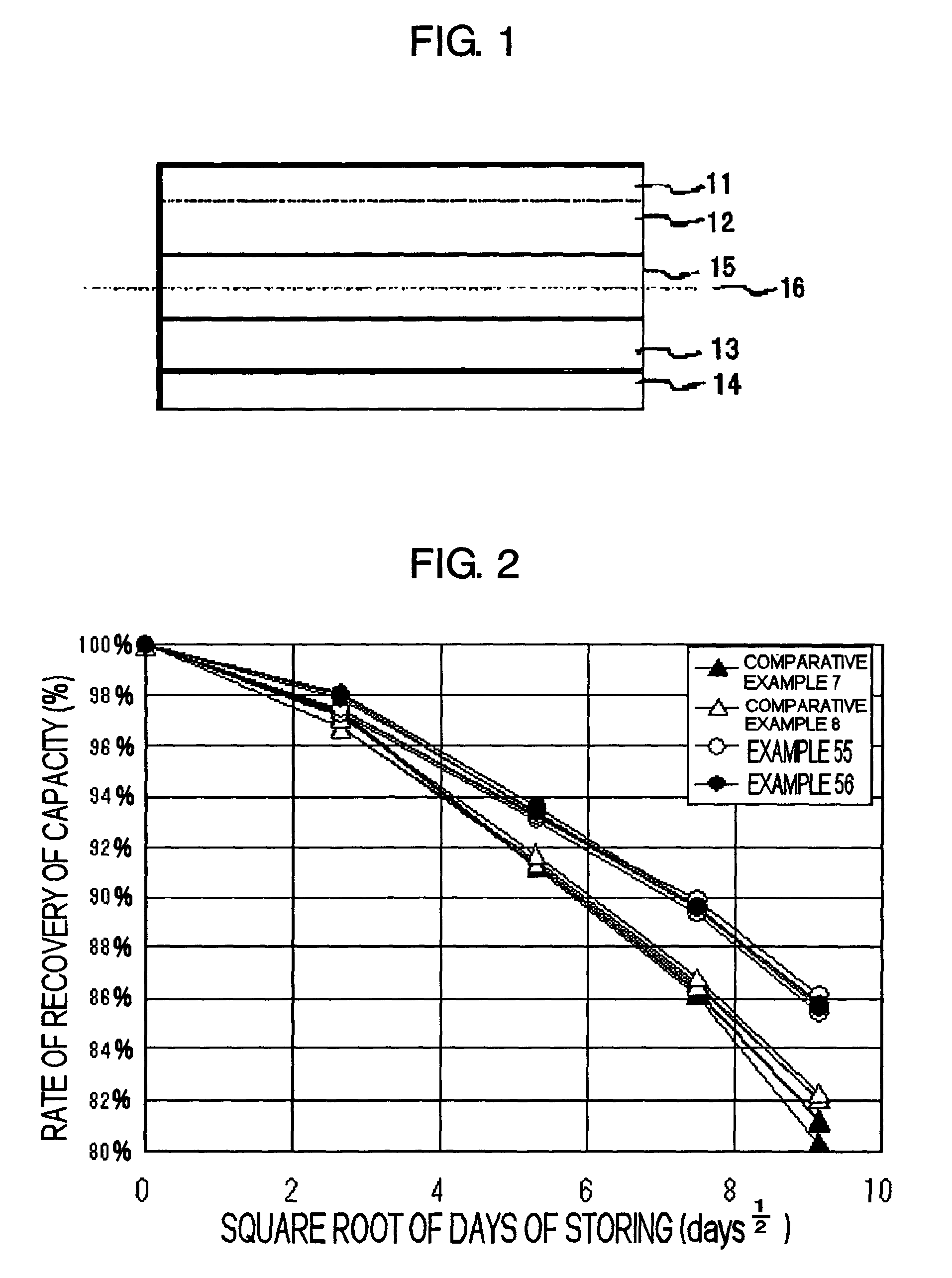
The present invention provides a technology of inhibiting the decomposition of the solvent of the electrolyte solution for the secondary battery. Further, the present invention provides a technology of prohibiting the resistance increase of the secondary battery and improving the storage properties such as improving the capacity retention ratio. The electrolyte solution 15 comprising non-proton solvent and cyclic sulfonic ester including at least two sulfonyl groups may be used.

Description

BACKGROUND OF THE INVENTION[0001]1. Field of the Invention[0002]The present invention relates to an electrolyte solution for a secondary battery and a secondary battery using the electrolyte solution.[0003]2. Description of the Related Art[0004]A non-aqueous electrolyte lithium ion secondary battery or a non-aqueous electrolyte lithium secondary battery having an anode made of a carbon material, an oxide, a lithium alloy or metallic lithium is attracting attentions as electric power sources for cell phones or notebook computers, since the use of such battery provides higher energy density.[0005]It is known that a film, which is referred to as surface film, protection film, solid electrolyte interface (SEI) or coating layer (hereinafter generically referred to as surface film), is formed on the surface of the anode of such type of the secondary battery. Since the surface film affects the efficiency of electrical charging and discharging, the cycle life and the safety of the secondary...

Claims


Application Information

Patent Timeline
IPC IPC(8): H01M6/16H01M4/02H01M10/05H01M4/36H01M10/052H01M10/0525H01M10/0567H01M10/0569H01M10/42
CPCH01M10/0567H01M10/0525Y02E60/122H01M2300/0037H01M2300/004H01M10/4235Y02E60/10H01M10/052
Inventor UTSUGI, KOJIKUSACHI, YUKIYAMAZAKI, IKIKO
Owner NEC CORP
Learn More