Resonant optical cavities for high-sensitivity high-throughput biological sensors and methods

Inactive Publication Date: 2008-06-10
UNIV OF UTAH RES FOUND
View PDF25 Cites 90 Cited by
  • Summary
  • Abstract
  • Description
  • Claims
  • Application Information

AI Technical Summary

Benefits of technology

[0027]The shapes of cylindrical optical cavities incorporating teachings of the present invention facilitate the generation of whispering gallery modes. In the present invention electromagnetic excitation radiation is preferably introduced into a cylindrical cavity through a peripheral edge of the cavity, facilitating the generation of two-dimensional whispering gallery modes within the cylindrical cavity at a substantially planar surface thereof. Whispering gallery modes prolong the exposure of molecules and molecule hybrids on the exposed surface of a cylindrical cavity to electromagnetic excitation radiation.
[0028]The cylindrical cavities of the biosensors of the present invention also have very high (e.g., about 104 and greater) quality factors (Q). An optical cavi

Problems solved by technology

The array size is limited by the patterning of immobilized capture molecules (Silzel et al., 1998) and the sensitivity is limited by the number of captured analytes per sensitivity zone and by the sensing technique employed.
Moreover, the use of a segmented waveguide is somewhat undesirable since the excitation radiation is not confined within the plane of the waveguide.
Consequently, the electromagnetic radiation emitted from one sensing zone may interfere with the electromagnetic radiation emitted from one or more adjacent sensing zones, thereby reducing the optical efficiency of a segmented waveguide and, thus, the degree of confidence with which each analyte may be detected when the segmented waveguide is used.
As a result, segmented waveguides are relatively insensitive.
Such sequential detection is somewhat undesirable, however, because of the time required to scan a biochip with a dense ar

Method used


Image

  • Resonant optical cavities for high-sensitivity high-throughput biological sensors and methods
  • Resonant optical cavities for high-sensitivity high-throughput biological sensors and methods
  • Resonant optical cavities for high-sensitivity high-throughput biological sensors and methods

Examples


example 1

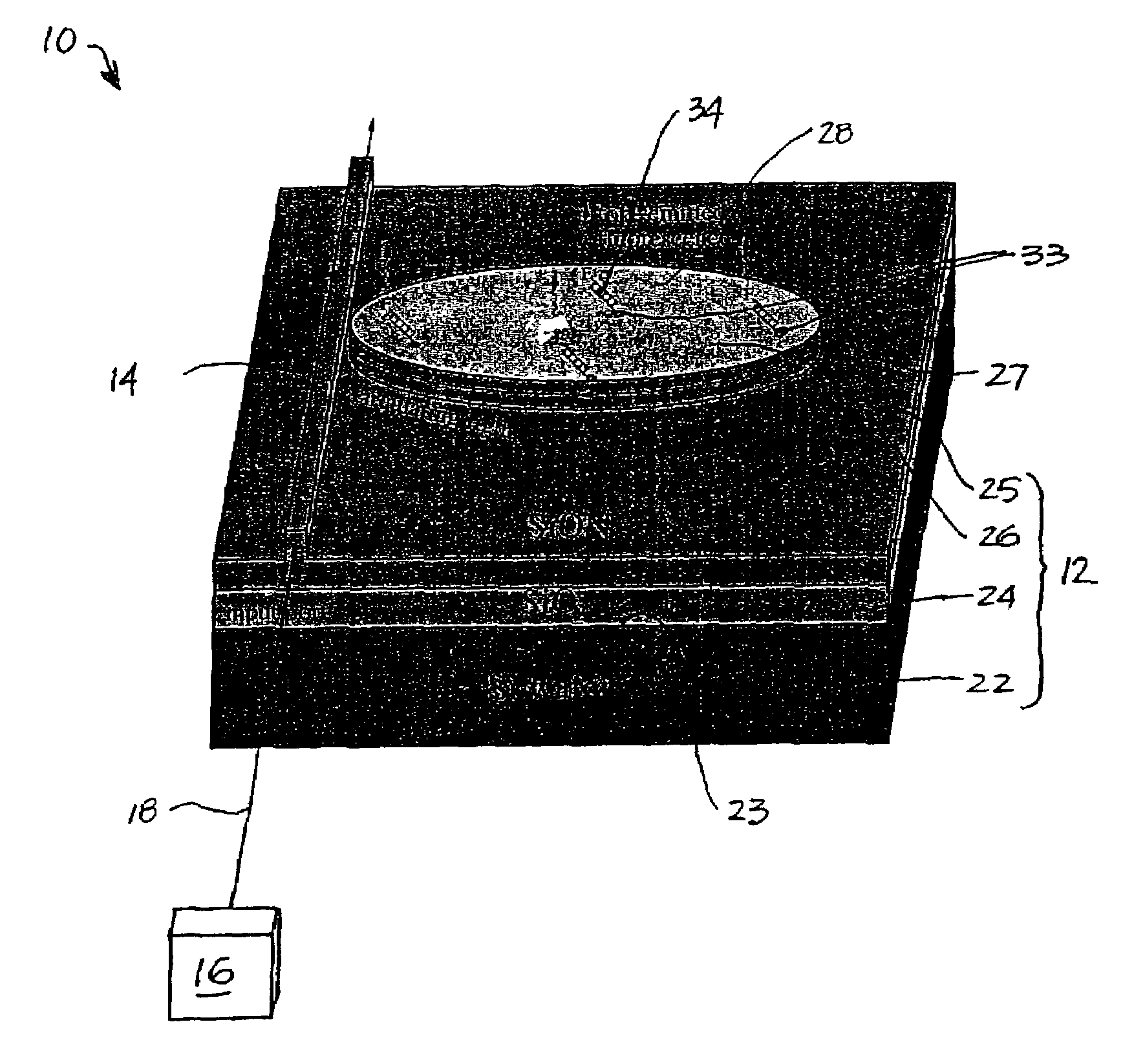
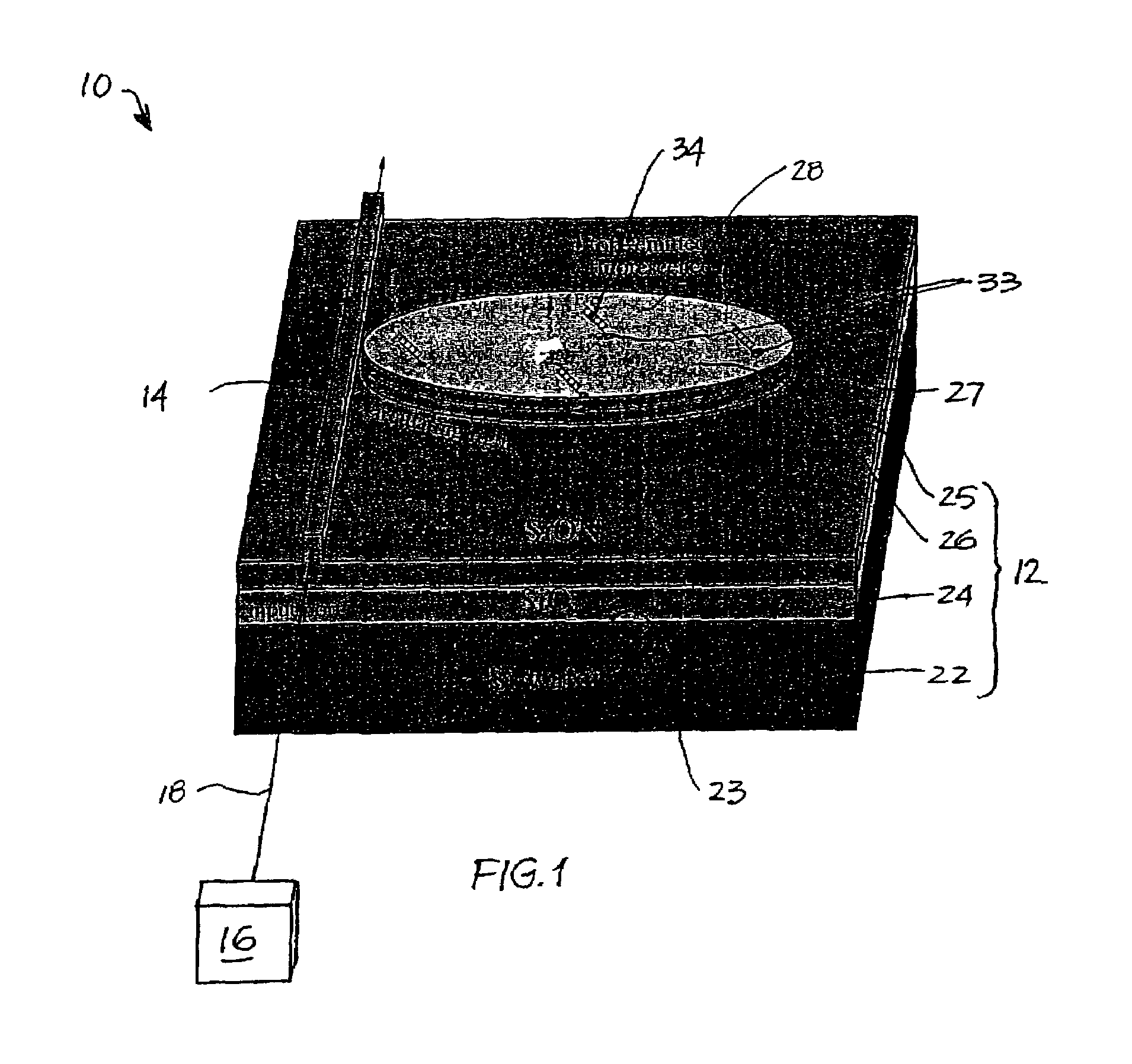
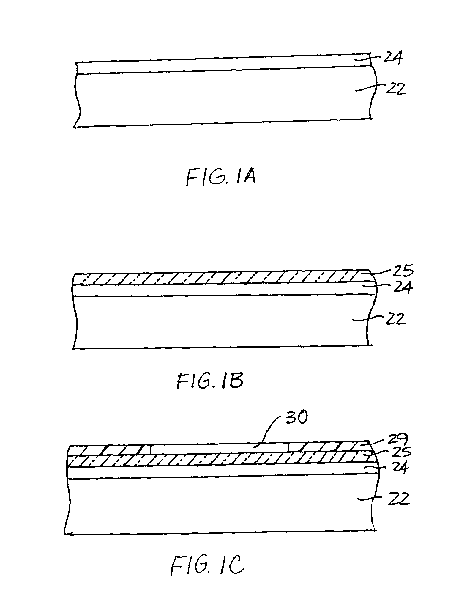
Development of Optical Microcavities

[0118]In determining the mass sensitivity of resonant optical cavities incorporating teachings of the present invention, calibration curves indicating the sensitivity per unit area of these resonant optical cavities may be generated and compared with the sensitivities of known mass sensing apparatus, such as the BIAcore surface-plasmon resonance apparatus.

[0119]Studies are initially performed using large diameter (about 25-50 μm) cylindrical cavities. There are many design parameters that affect the cavity FSR, Q, and mode structure. This parameter space is explored initially using FDTD simulation.

[0120]When optimized design parameters are obtained, the cylindrical cavities are fabricated. Using a laser diode with tunability over the absorption band of the target fluorescent tag and a high-sensitivity photoreceiver, the cavity free-spectral range (FSR) and Q of the cylindrical cavities are measured and compared with the results obtained through FD...

example 2

Nucleic Acid Probe Assay

[0122]After proper device characterization, nucleic acid assay studies are performed. Nucleic acid probes are chosen because they stand to benefit the most from the high throughput capability of the microfabricated array embodiment of biosensor disclosed previously herein. The T3 RNA polymerase promotor site is the model system for nucleic acid hybridization. These synthetics mimic single-stranded oligonucleotides amplified from human DNA using polymerase chain reaction (PCR) and, while T3 has minimal clinical relevance, the T3 hybridization process has been well characterized and serves as an ideal baseline for initial studies, which can be readily extrapolated to assays with clinical relevance.

[0123]Capture oligonucleotides (T3 for the baseline studies) are immobilized relative to the substantially planar surface of a SiON cylindrical cavity by coating the substantially planar surface with neutravidin using a simple puddle coating technique and immobilizing...

example 3

Comparison between Singly Resonant and Doubly Resonant Optical Cavities

[0126]Two approaches may be used to demonstrate enhanced sensitivity detection of doubly resonant optical cavities over singly resonant cavities: 1) operation at reduced temperatures, and 2) utilization of dyes that are not strongly broadened.

[0127]In the first case, the fluorescence yield of Cy5 is measured versus temperature down to 77° K. As the temperature is lowered, the number of occupied phonon levels is reduced, causing narrowing of the inhomogeneous linewidth.

[0128]The second approach uses a different class of dyes. For example, B-phycoerythrin has an emission peak at 575 nm with spectral width of about 20 nm. The broad absorption peak is centered about 546 nm (which can still be accessed efficiently by a doubled Nd:YAG laser at 532 nm), such that the expected enhancement factor is about 2, assuming that double resonance is obtained at 575 nm and 532 nm with FSR 42 nm and that all the fluorescence couple...


PUM


Abstract

Biosensors including resonant optical cavities. The resonant optical cavities are shaped so as to generate whispering gallery modes, which increase the quality factors of the cavities and facilitate the detection of analytes in a sample with enhanced sensitivity. The sizes of the resonant optical cavities facilitate their use in biosensors that include arrays of sensing zones. Accordingly, the resonant optical cavities may be used in high-density sensing arrays that can be read in real-time and in parallel. Thus, the resonant optical cavities are useful for detecting small concentrations of samples in real-time and with high throughput. Different embodiments of the biosensors are also disclosed, as are methods for using the biosensors.

Description

TECHNICAL FIELD[0001]The present invention relates generally to optical biosensors and, particularly, to high throughput optical biosensors. More particularly, the optical biosensors of the present invention include structures that facilitate the use of whispering gallery modes for enhancing the sensitivity of the optical biosensors. The present invention also relates to methods for fabricating the optical biosensors, as well as to diagnostic methods that employ the optical biosensors.BACKGROUND ART[0002]Early and accurate diagnostics are crucial to the treatment of many medical disorders. High-throughput biosensing is an active and growing area of research for clinical applications in detecting antibodies, genes, drugs, peptides, cells, and other biological molecules of interest, as well as for sequencing DNA molecules.[0003]Currently, the two major optical approaches to biosensing upon which research efforts are focused are the use of segmented evanescent waveguide biosensors and ...

Claims


Application Information

Patent Timeline
IPC IPC(8): G01N33/551G01N33/552
CPCG01N21/6452G01N21/648G01N21/7746G01N33/54373G01N2021/6439G01N2021/7786Y10S435/808Y10S436/805
Inventor BLAIR, STEVEN M.
Owner UNIV OF UTAH RES FOUND
Why Eureka
Try Eureka