Low voltage electron source with self aligned gate apertures, fabrication method thereof, and devices using the electron source

a low-voltage electron source and gate aperture technology, which is applied in the manufacture of electrode systems, electric discharge tubes/lamps, and discharge tubes luminescent screens, etc., can solve the problems of device drivers, power consumption, and current state of the art of cnt electron sources that do not meet the above requirements

Inactive Publication Date: 2012-01-24
TOLT ZHIDAN L
View PDF9 Cites 2 Cited by
  • Summary
  • Abstract
  • Description
  • Claims
  • Application Information

AI Technical Summary

Benefits of technology

[0027]It is the objective of the current invention to: a) provide a method to fabricate one or multiple self-aligned gate aperture around a single or a small cluster of CNT and with equal distance to each CNT; b) provide a method for controlling CNT growth over large area so that they are either mono-dispersed or dispersed in small clusters, with a narrow distribution in CNT diameter and the number of CNT in each cluster, and, furthermore, the spacing between the single or cluster of CNT is large enough to enable a gate aperture around each one of them and yet small enough in order that the emitter density can be as high as 108 / cm2; and c) provide a means for enabling favorable wide band gap semiconductor nano-structures to be utilized as field emitters.
[0028]It is another object of the invention to provide an electron source using a single or a small cluster of dispersed nano-structures that: a) has emission properties which can be modulated with a low voltage, b) has a high emission site density, c) emits uniformly over large area, d) generate a highly collimated electron beam, e) has high energy efficiency, f) is robust to ion bombardment and chemical attack, and g) is easy to fabricate with high production yield.
[0032]Self-alignment of an aperture, as is described in the current invention, means the location where the incline CNT is grown or assembled can be random and needs not be predetermined. The spacing between CNTs, in this invention, may be as low as one micrometer or less. Therefore, two orders of magnitude higher emitter density over prior art is possible and advantages can be taken of CNT growth or assembly controlling processes that don't require expensive and complicated lithography.
[0033]One of such enabled embodiments is to use an ion-track-etched membrane as a hard mask for patterning catalyst before CNT growth. Preferred membranes are those with a pore density between 1×10⁵ to 1×10⁹ pores / cm2 and pore sizes from 10 nm to a few micrometers. It is known that for CNT growth, its diameter and the inter-tube spacing are determined by those of catalyst. When the catalyst size is less than 200 nm, a single CNT is likely grow from each particles. When membrane with larger pores is used, a small cluster of CNT, 3 to 5 for instance, can grow from each particle. Catalyst deposition through an ion-track-etched membrane with chosen pore size and density will produce an array of catalyst particles with substantially uniform size and desirable average inter-tube or inter-cluster spacing.
[0034]The advantages of using the ion-track-etched membranes as a shadow mask for catalyst deposition include: a) pore size and density are in the most desirable range and are highly controlled, b) inexpensive, widely available, and come in sizes particularly suitable for large flat panel display applications, and c) it is easy to apply them to a substrate surface as a shadow mask and they can be recycled in production, provided the catalyst is removed after each deposition. Both the substrate and the membrane can be surface treated so that they attract to each other, resulting a smooth and uniform overlay on the substrate.
[0040]In accordance with the current invention, the emitter, whether it is a single nano-structure or a small cluster of nano-structures, will always perfectly located at the center of the aperture regardless its location, and size, and the distance between the aperture and emitter (the emitter-to-gate distance d) is substantially the same over the entire substrate surface, on the order of 100 nm, and controllable by the thickness of the gate insulator. And, all the emitters have substantially the same length and diameter. A gated field emission electron source with these characteristics provides an extra low voltage modulation, uniform emission over large area, and low energy loss from gate current. Since the emitter is largely embedded in a dielectric, it is mechanically and chemically protected and, to some extent, shielded from ion bombardment, giving rise to a longer lifetime and steadier electron emission. With a proper selection, the embedding material can also enhance the thermal conduction from the emitter. When a dielectric is used as the embedding material, the relatively large gap between the cathode and the gate electrodes also reduces the occurrence of a short circuit between them and the capacitive energy consumption during the emission modulation, resulting in a higher production yield and higher energy efficiency. An array of emitters with a density as high as 108 / cm2 will produce a more homogeneous emission compared to those of low emitter density.

Problems solved by technology

The cost of a device driver, which often is a major cost component, power consumption, as well as device miniaturization, and ability to operate at high frequency are all depend on the modulation voltage.
Despite the superior emission properties of a single CNT, the current state of the art of a CNT electron source does not meet most of the above requirements and, therefore, has not found any product applications yet, despite the appearance of some prototype flat panel displays.
Both methods are difficult to implement in production.
E-beam lithography is so slow and expensive that it is ill suited for any meaningful operation.
Applying a mono-layer consistently over large an area is no easy task.
b) Difficulty in Fabrication of an Integrated Gate Structure
Two obstacles make the fabrication difficult.
First, CNT films is sensitive to wet processes.
Upon exposure to a wet agent, CNTs either stick to the substrate or to themselves, diminishing their field emission properties.
The problem is that a group of densely grown CNTs in a single gate hole does not emit well because of the strong electrostatic effect amongst them and the variation in their length and aspect ratio.
CNTs mixed with other chemicals to facilitate screen-printing into gate hole do not perform well either.
In addition, deposition of CNT into the gate hole often cause short circuit between the gate and the cathode electrode, resulting in low production yield.
For many high frequency applications, these high modulation voltages make the application impossible due to high energy loss and loss of signal fidelity.
As for display application, the device become impractical, since conventional CMOS display drivers will not be able to deliver it.
And due to higher current, these sites also burn out faster and, therefore, have a short lifetime.
Carbon reacts easily with oxygen, causing emitter erosion.
Accumulated re-deposition of the sputtered Carbon can then causes short circuit between electrodes.
Both growth and screen-printing of CNT into a pre-fabricated gate holes can often cause short circuit between cathode and gate electrodes.
The strict requirements of high-resolution photolithography also contribute to lower production yield and high cost.

Method used


Image

  • Low voltage electron source with self aligned gate apertures, fabrication method thereof, and devices using the electron source
  • Low voltage electron source with self aligned gate apertures, fabrication method thereof, and devices using the electron source
  • Low voltage electron source with self aligned gate apertures, fabrication method thereof, and devices using the electron source

Examples


Embodiment Construction

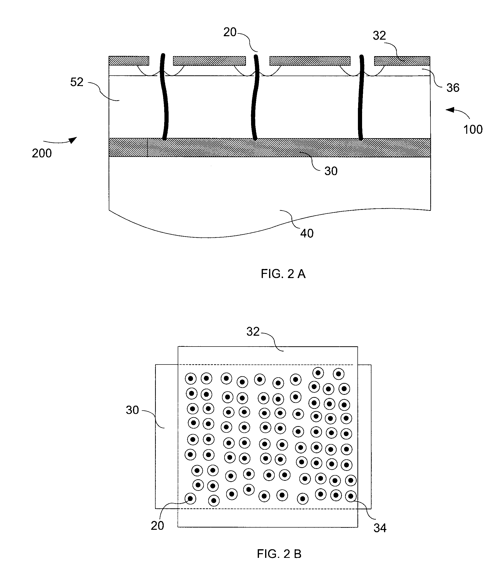
[0089]FIG. 2 illustrates an electron source 200 by current invention using vertically aligned and mono-dispersed CNT 20 as emitter. It includes a cathode electrode 30 deposited on a substrate 40; an emitter layer 100 disposed over the cathode and formed from an embedding dielectric 52 and an array of CNTs embedded therein, the emitter layer having a surface parallel to which the CNTs have been truncated to the same length, and above the surface the CNTs protrude by a small fraction of one micrometer; a gate insulator 36 disposed over the emitter layer of a thickness on the order of 100 nm and having an array of apertures, each aligned with and exposes one nano-structure in the emitter layer; and a gate electrode 32 deposited on the gate insulator and having an array of apertures 34 aligned with the apertures in the insulator and spaced from the exposed CNT by a distance equal to the thickness of the insulator. When a positive voltage is applied between the gate and the cathode elect...


PUM


Abstract

A method of fabricating an electron source having a self-aligned gate aperture is disclosed. A substrate is deposited on a first conductive layer. Over the first conductive layer an emitter layer is deposited. The emitter layer includes one or a plurality of spaced-apart nano-structures and a solid surface with nano-structures protruding above the surface. An insulator is conformally deposited over the emitter layer surface and forms a post from each protruding nano-structure. A second conductive layer is deposited over the insulator and the second conductive layer and the insulator are removed from the nano-structures such that apertures are formed in the second conductive layer and at least the ends of the nano-structures are exposed at the centers of said apertures.

Description

CROSS REFERENCE TO RELATED APPLICATIONS[0001]This application is also a continuation in part of U.S. application Ser. No. 11 / 927,323, filed on Oct. 29, 2007, published on Oct. 23, 2008, as U.S. 2008 / 0261337 A1, and titled “LOW VOLTAGE ELECTRON SOURCE WITH SELF ALIGNED GATE APERTURES, FABRICATION METHOD THEREOF, AND LUMINOUS DISPLAY USING THE ELECTRON SOURCE.”[0002]This application is a continuation-in-part of U.S. application Ser. No. 10 / 707,342, filed on Dec. 5, 2003, published on Jun. 16, 2005, as U.S. 2005 / 0127351 A1, and titled “LOW VOLTAGE ELECTRON SOURCE WITH SELF ALIGNED GATE APERTURES, FABRICATION METHOD THEREOF, AND LUMINOUS DISPLAY USING THE ELECTRON SOURCE,” the disclosure of which is incorporated herein by reference in its entirety.[0003]This application is related to U.S. application Ser. No. 11 / 842,938, filed on Aug. 21, 2007, U.S. application Ser. No. 10 / 807,890, filed on Mar. 24, 2004, U.S. application Ser. No. 11 / 467,880 filed on Aug. 28, 2006 and U.S. application S...

Claims


Application Information

Patent Timeline
Patent Type & Authority Patents(United States)
IPC IPC(8): H01J1/46
CPCH01J3/022H01J9/025H01J31/127B82Y10/00H01J2201/30469
Inventor TOLT, ZHIDAN LI
Owner TOLT ZHIDAN L
Why Eureka
Try Eureka