Three-layer magnetic element, magnetic field sensor, magnetic memory and magnetic logic gate using such an element

a three-layer magnetic element and logic gate technology, applied in the field of magnetic materials, can solve the problems of low longitudinal resistivity of materials, inability to use them in the area of magnetic field sensors or magnetic memories or logic components, and difficulty in deliberately changing the magnetisation direction by applying a perpendicular magnetic field

Active Publication Date: 2013-08-20
COMMISSARIAT A LENERGIE ATOMIQUE ET AUX ENERGIES ALTERNATIVES +1
View PDF4 Cites 16 Cited by
  • Summary
  • Abstract
  • Description
  • Claims
  • Application Information

AI Technical Summary

Benefits of technology

[0049]The material used makes it possible to combine the advantages of the various materials stated above, namely high perpendicular anisotropy making it possible to compensate or even exceed the inherent shape anisotropy of thin films and, in the particular case where the Hall effect is measured, high longitudinal resistivity and a high extraordinary Hall coefficient.
[0052]High longitudinal resistivity is obtained by using magnetic thin films that are therefore highly resistive due to the important role played by interfacial diffusions that occur in contact with one or more oxide, nitride or hydride layers. The electrical resistance of the entire stack is therefore high.
[0072]Using the method according to the invention, the element is cut into a post with a square, rectangular, circular or elliptical base having lateral dimensions of several hundred nm or less. It may also be cut, still retaining the same range of dimensions, into a shape that makes it possible to detect the magnetic signal by measuring the extraordinary Hall effect.

Problems solved by technology

This also, however, makes it more difficult to deliberately modify the magnetisation direction by applying a perpendicular magnetic field, such as, for instance, when the material is used as a magnetic memory in which information is in fact coded by the magnetisation direction.
Unfortunately, these materials have low longitudinal resistivity due to the low resistivity of their metallic components.
Finally, the authors do not intend these materials for use in the area of magnetic field sensors or magnetic memories or logic components based, in particular, on measuring the extraordinary Hall effect.
Moreover, for magnetic memory or magnetic logic gate type applications, known materials of the (Pt / Co) type or lanthanide series / transition metal alloys do not have all the required properties for this type of application (high electron spin polarisation (if magnetoresistance is used to detect the signal), good thermal stability during annealing, low corrosion).

Method used


Image

  • Three-layer magnetic element, magnetic field sensor, magnetic memory and magnetic logic gate using such an element
  • Three-layer magnetic element, magnetic field sensor, magnetic memory and magnetic logic gate using such an element
  • Three-layer magnetic element, magnetic field sensor, magnetic memory and magnetic logic gate using such an element

Examples


first embodiment

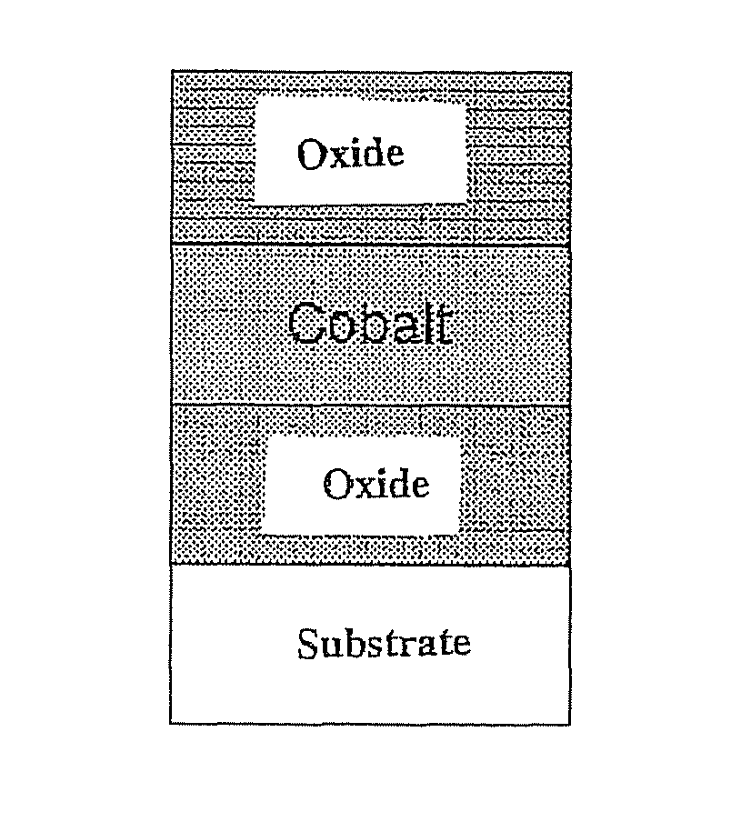
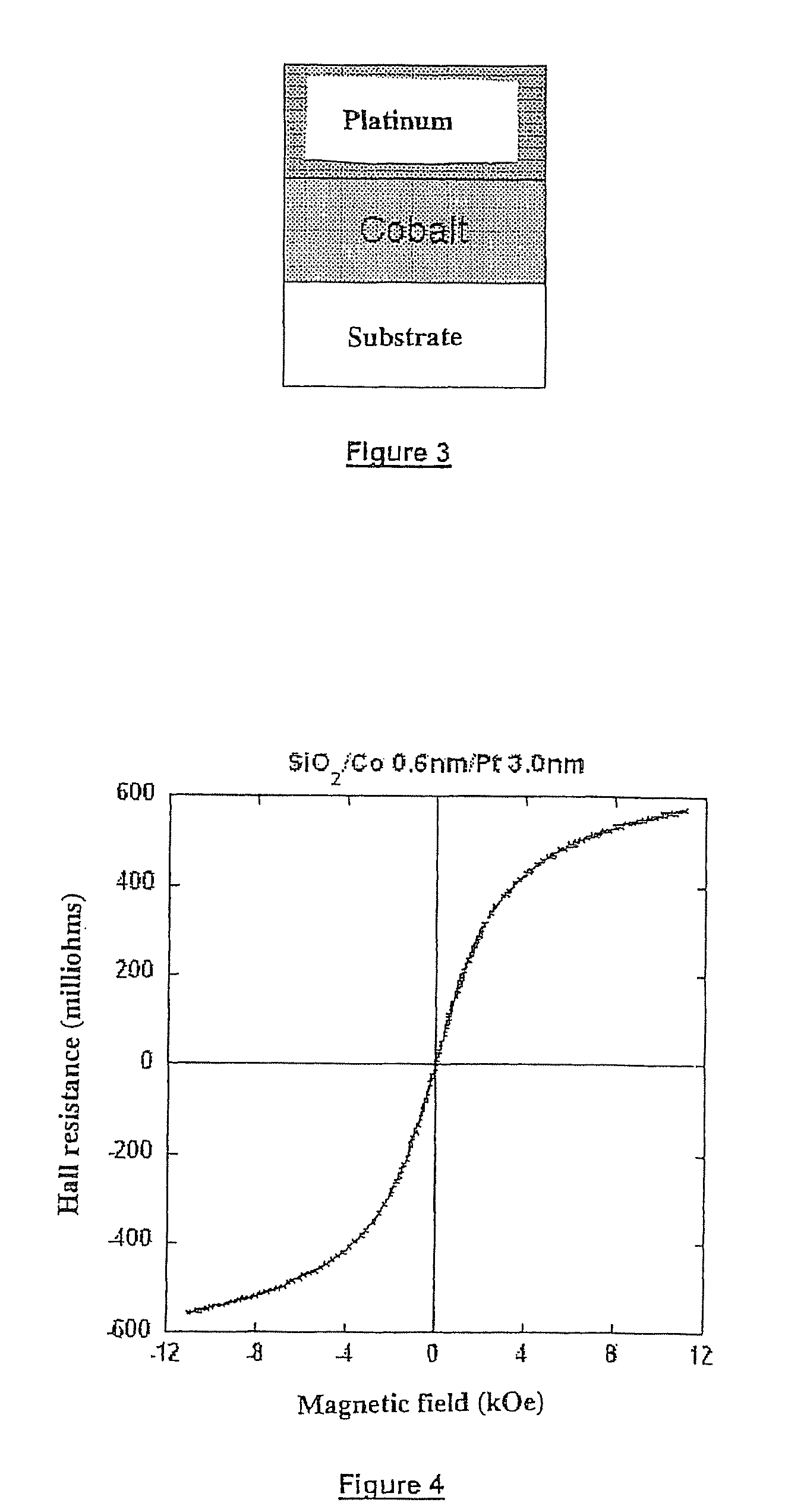
[0107]FIG. 3 is a schematic view of the invention. A magnetic layer M consisting, here, of cobalt and having a generally small thickness is deposited on a substrate which has the required characteristics to replace layer O and is covered, for example, in oxidised or nitrided silicon or composed, for example, of glass or magnesium oxide. If this thickness exceeds a specific value which depends on the material used for layer M and the intensity of the interfacial interactions with the materials that are in contact with this magnetic layer M, magnetisation is no longer, as is known, perpendicular to the layer plane due to the volume shape anisotropy of layer M which tends to keep magnetisation of the layer in-plane.

[0108]For this layer M, its thickness is selected and, above all, determined by the ability to obtain a continuous metal layer. In fact, as discussed earlier, some magnetic metals do not wet satisfactorily on oxides such as silicon dioxide or alumina. In some cases, the magn...

second embodiment

[0118]FIG. 6 is a schematic view of the invention.

[0119]One deposits layer O, preferably made of aluminium oxide, on the above-mentioned substrate, the thickness of the layer is 0.3 to 5 nm but the latter figure is not very critical. This layer generally consists of deposited metal such as aluminium that has been oxidized for instance. However, aluminium can be replaced by any other element capable of combining with oxygen to form high-quality oxides in thin layers, namely and for example, magnesium, ruthenium, silicon, tantalum, chrome, zirconium, titanium, hafnium, vanadium, cobalt, nickel, iron, copper, tungsten and, more generally, any material or alloy capable of forming stable oxides. One can also use an alloy or a multilayer of these materials as an elementary oxide layer for certain particular embodiments.

[0120]Instead of using a plasma oxidation technique, it is also possible to produce the oxide by using a known technique of reactive sputtering of the element in question i...

fifth embodiment

[0128]In a fifth embodiment shown schematically in FIG. 10, it is possible to bring layer M in question, here a layer made of cobalt, into contact with a layer of antiferromagnetic material M′ such as IrMn, PtMn, FeMn or NiMn alloys which are known to induce exchange anisotropy coupling with said layer M.


PUM


Abstract

A three-layer magnetic element comprises, on a substrate, a first oxide, hydride or nitride layer O having a metal magnetic layer M mounted thereon, the latter having either a second oxide, hydride or nitride layer O′, or a non-ferromagnetic metal layer M′ mounted thereon. Layer M is continuous, has a thickness of 1 to 5 nm and the magnetization thereof is parallel to the layer plane in the absence of layers O and O′. There is, for a range of temperature equal to or greater than ambient temperature, interfacial magnetic anisotropy perpendicular to the layer plane on interfaces O / M and M / O′ that is capable of decreasing the effective demagnetizing field of layer M or orienting the magnetization of layer M in a manner substantially perpendicular to the layer plane.

Description

FIELD OF THE INVENTION[0001]The present invention relates to the field of magnetic materials, more especially those intended to be used as magnetic field sensors or in magnetic memories used to store and read data in electronic systems or even to produce components that can be used in the field of reprogrammable logic devices.BACKGROUND OF THE INVENTION[0002]One of the applications to which the present invention relates concerns magnetic elements that are used to detect magnetic fields on the basis of measuring the extraordinary Hall effect.[0003]There are two types of Hall effect: the ordinary Hall effect and the extraordinary Hall effect. The ordinary Hall effect occurs in metallic materials or doped semiconductors and is due to the Lorentz force that acts on electrons under the influence of a magnetic field. The extraordinary Hall effect occurs to a limited extent in ferromagnetic materials and is the result of diffusion of electrons due to spin-orbit interaction with the magneti...

Claims


Application Information

Patent Timeline
Patent Type & Authority Patents(United States)
IPC IPC(8): G01R33/07G01R33/02
CPCB82Y25/00G01R33/098G11C11/18H01F10/3286H01F41/32H01L43/06H01L43/14H01F10/3236H01F10/3218H10N52/00H10N52/01
Inventor RODMACQ, BERNARDAUFFRET, STEPHANEDIENY, BERNARDNISTOR, LAVINIA ELENA
Owner COMMISSARIAT A LENERGIE ATOMIQUE ET AUX ENERGIES ALTERNATIVES
Why Eureka
Try Eureka