
High performance coatings and surfaces to mitigate corrosion and fouling in fired heater tubes

a technology of high-performance coatings and surfaces, applied in surface reaction electrolytic coatings, magnetic recording, record information storage, etc., can solve the problems of limiting the residence time, coke formation and accumulation on the visbreaker wall, and reducing the heating efficiency of the heater, so as to reduce the formation of coke suppress the formation of fouling, and reduce the effect of carburization and sulfidation and other forms of high temperature corrosion

Inactive Publication Date: 2014-06-10
EXXON RES & ENG CO
View PDF8 Cites 2 Cited by
  • Summary
  • Abstract
  • Description
  • Claims
  • Application Information

AI Technical Summary

Benefits of technology

[0017]In accordance with the present invention, each fired heater tube may be formed from a high performance coated material that is resistant to carburization, naphtanic acid corrosion, sulfidation, and other forms of high temperature corrosion and fouling. The use of a high performance coated material that is resistant to corrosion and fouling significantly mitigates carburization, naphtanic acid corrosion, sulfidation and other forms of high temperature corrosion and suppresses fouling, which produces numerous benefits including (i) an increase in heating efficiency, (ii) a reduction in the overall amount of energy needed to heat the crude oil, (iii) an increase in refinery throughput and (iv) a significant reduction in refinery downtime.

Problems solved by technology

Since this process cannot tolerate coke formation, it is required to be within the coke induction period that may limit conversion, rather than heavy fuel oil specifications.
However, the drum is much smaller in volume to limit the residence time with the entire liquid product flowing therethrough.
Upsets cause coke to form and accumulate on visbreaker walls, which requires periodic decoking.
The radiant section tubes in a fired heater used in many refinery process units can experience fouling on the inside and / or outside of the tube surface.
External tube fouling occurs when the heater is oil fired.
Fired heaters that heat crude and reduced crude usually experience the highest level of internal fouling.
All these materials can end up sticking to the tube wall and forming “coke”.
For example, fired heaters heating liquid naphtha can experience internal tube fouling due to corrosion products and / or polymerization reactions forming long chain molecules which stick to the tube wall.
Internal tube fouling usually has a large impact on heater operation and thermal efficiency.
These formations / foulant / coke deposits can result in an increase in the radiant tube metal temperature (TMT).
A secondary effect of internal fouling is increased pressure drop, which limits capacity and throughput.
When coke forms in the heater tubes, it insulates the inside of the tube which results in elevated temperatures on the outside of the tube.
During normal use, the internal surfaces of the fired heater tubes are subject to carburization sulfidation, naphthenic acid corrosion and other forms of high temperature corrosion as a result of the prolonged exposure to the stream of heavy crude oil, resid and other petroleum fractions.
Carburized material suffers an increase in hardness and often a substantial reduction in toughness, becoming embrittled to the point of exhibiting internal creep damage due to the increased volume of the carbides.
(260° C.) and will cause sulfidation corrosion which forms iron sulfide.
Corrosion on the internal surfaces of the fired heater tubes creates an uneven surface that can enhance fouling because the various particles found in the petroleum stream may attach themselves to the roughened surface.
These synthetic crudes present additional fouling problems, as these feedstocks are too heavy and contaminant laden for the typical refinery to process.
However, this coating, as characteristic of all such relatively thin coatings, reveals poor mechanical integrity and thermal stability due to presence of voids, defects and intermetallic brittle phases in the layer and has low reliability.

Method used


Image

  • High performance coatings and surfaces to mitigate corrosion and fouling in fired heater tubes
  • High performance coatings and surfaces to mitigate corrosion and fouling in fired heater tubes
  • High performance coatings and surfaces to mitigate corrosion and fouling in fired heater tubes

Examples


example 1

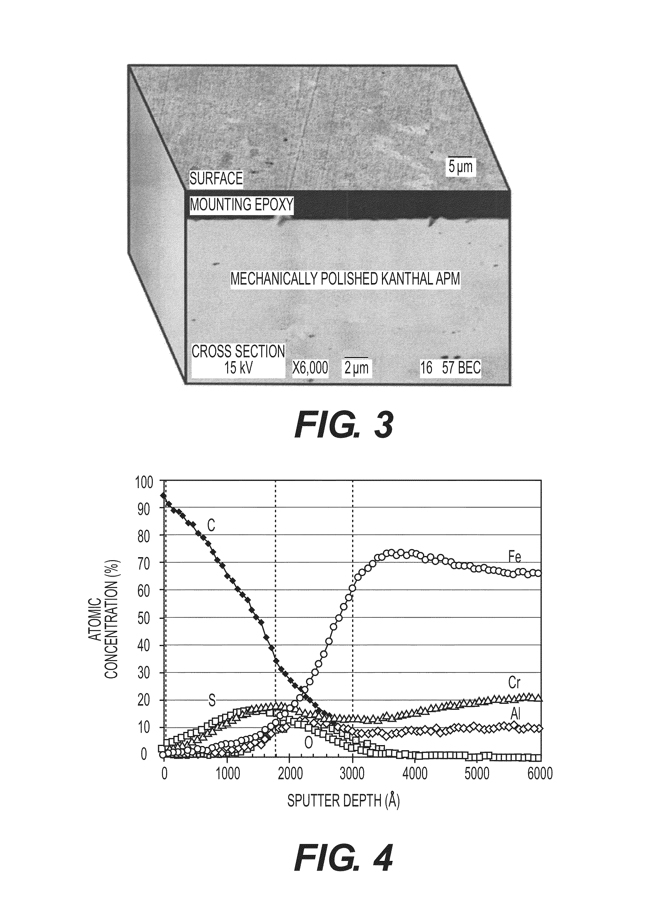
[0053]Following the test methods described above, a mechanically polished Kanthal APM sample was tested. FIG. 3 depicts surface and cross-sectional SEM images of the corrosion surface of a mechanically polished Kanthal APM after reaction at 1000° F. (538° C.) in heavy resid-content crude for 4 hours. No significant corrosion or fouling deposits were observed after the specimen was cleaned in toluene and acetone sequentially. FIG. 4 depicts AES concentration depth profile of the corrosion surface of the same sample. The carbon peak found near the surface was probably caused by remnants of crude deposits. Also identified was about 200 nm thick corrosion scale, which was mainly comprised of Cr—Fe sulfide and Cr—Al oxide. Under this layer, about 200 nm thick alumina sublayer formation was observed. This alumina layer provides superior corrosion resistance of the coating metal, which is prerequisite for fouling mitigation.

example 2

[0054]Following the test methods described above, a 120 grit finished Kanthal APM sample was tested. FIG. 5 depicts surface and cross-sectional SEM images of the corrosion surface of a 120 grit finished Kanthal APM after reaction at 1000° F. (538° C.) in heavy resid-content crude for 4 hours. After cleaned the specimen in in toluene and acetone sequentially, no significant corrosion scale was observed. However, some thin layer of carbon deposit was observed on the surface, whose deposit appeared to be anchored to the roughened surface of the metal. Superior corrosion resistance was attributed to alumina layer formed on the metal surface. The thickness of alumina layer was about 200 nm measured by AES.

[0055]The cross-section SEM images illustrated in FIGS. 3 and 5 illustrate the effect of surface roughness in reduction of carbon deposit. Two samples were tested and cleaned at the same experimental conditions. The thickness of the carbon deposit on the rough surface (e.g. 120 grit fin...

example 3

Comparative Example

[0056]Following the test methods described above, a 120 grit finished 304L SS sample was tested. FIG. 6 depicts surface and cross-sectional SEM images of the corrosion surface of a 120 grit finished 304L SS after reaction at 1000° F. (538° C.) in heavy resid-content crude for 4 hours. Formation of thick (about 8μ) multi-layered corrosion scale was observed. Corrosion scales were comprised of Fe sulfide, Fe—Cr sulfide, thiospinel and Fe—Cr oxysulfide based on Energy Dispersive X-ray Spectroscopy (EDXS) characterization. In comparison with the same surface finished Kanthal APM (Example 2), the thickness of corrosion scale on 304L SS was about 40 times thicker (8000 nm vs. 200 nm). This result clearly confirms that the alumina layer formed on Knathal APM surface is much more resistant to corrosion than the corrosion scales formed on 304L SS surface.


PUM

PropertyMeasurementUnit
thicknessaaaaaaaaaa
thicknessaaaaaaaaaa
thicknessaaaaaaaaaa

Abstract

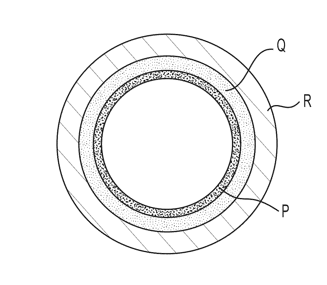
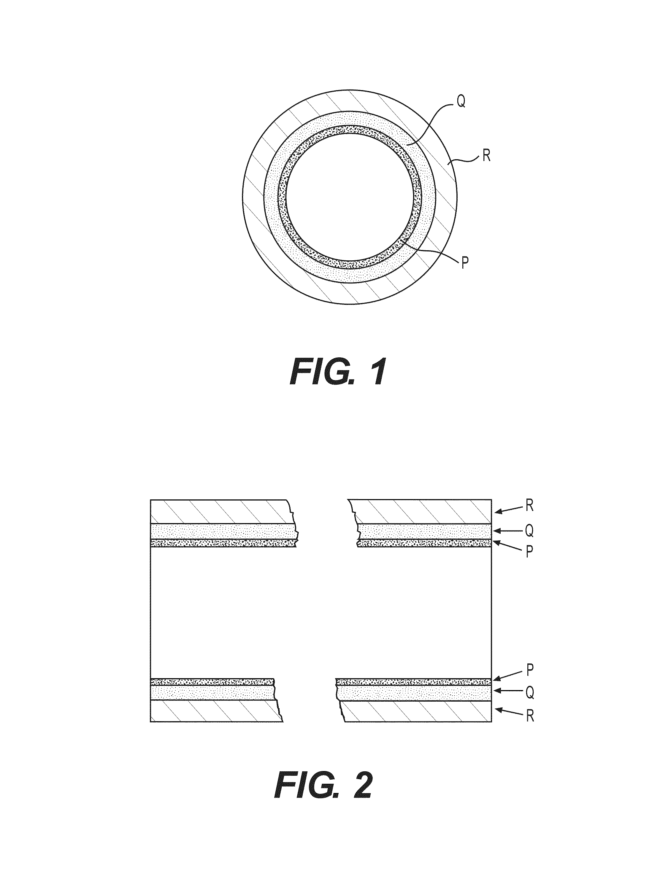
A fired heater tube that is resistant to corrosion and fouling is disclosed. The fired heater tube comprises an advantageous high performance coated material composition resistant to corrosion and fouling comprises: (PQR), wherein P is an oxide layer at the surface of (PQR), Q is a coating metal layer interposed between P and R, and R is a base metal layer, wherein P is substantially comprised of alumina, chromia, silica, mullite, spinels, and mixtures thereof, Q comprises Cr, and at least one element selected from the group consisting of Ni, Al, Si, Mn, Fe, Co, B, C, N, P, Ga, Ge, As, In, Sn, Sb, Pb, Sc, La, Y, Ce, Ti, Zr, Hf, V, Nb, Ta, Mo, W, Re, Ru, Rh, Ir, Pd, Pt, Cu, Ag, Au and mixtures thereof, and R is selected from the group consisting of low chromium steels, ferritic stainless steels, austenetic stainless steels, duplex stainless steels, Inconel alloys, Incoloy alloys, Fe—Ni based alloys, Ni-based alloys and Co-based alloys.

Description

CROSS REFERENCE TO RELATED APPLICATION[0001]This application relates to and claims priority to U.S. Provisional Patent Application No. 61 / 129,224, filed on Jun. 12, 2008.FIELD OF THE INVENTION[0002]This invention relates to the reduction of carburization and sulfidation corrosion and the reduction of depositional fouling in general and in particular the reduction of carburization and sulifidation corrosion and the reduction of depositional fouling in fired heater tubes in refinery process units, petrochemical processing facilities, and in other ancillary and related industries such as synthetic fuels processes, (e.g., coal to liquids, coal gasification and gas to liquids) and other components used for transporting or conveying process streams, which may be prone to corrosion and fouling. The present invention also relates to the reduction of corrosion and fouling associated with process streams, which include but are not limited to heavy crude oils and resid streams. More specifical...

Claims


Application Information

Patent Timeline
Patent Type & Authority Patents(United States)
IPC IPC(8): B32B15/18B32B15/04B32B15/01C23C28/00F16L9/14F28F1/00F28F13/14C23C30/00C07F15/00B32B15/20
CPCC23C28/3455C23C30/00C23C28/321C23C28/322C23C28/345Y10T428/12479Y10T428/12944Y10T428/1266Y10T428/12937Y10T428/12618Y10T428/12993Y10T428/13Y10T428/265Y10T428/12951Y10T428/264Y10T428/12847Y10T428/12292Y10T428/1259Y10T428/12611
Inventor CHUN, CHANGMINBANGARU, NARASIMHA-RAO VENKATAGREANEY, MARK ACODY, IAN AHUBBARD, JR., F. PIERCEDEUTSCH, DAVID SAMUEL
Owner EXXON RES & ENG CO
Learn More