Eureka AIR delivers breakthrough ideas for toughest innovation challenges, trusted by R&D personnel around the world.

Surface-mediated cell-driven power tools and methods of operating same

a surface-mediated cell and power tool technology, applied in the direction of primary cell maintenance/service, sustainable manufacturing/processing, batteries, etc., can solve the problems of huge voltage ripple of the battery pack, unsatisfactory for most batteries, and fluctuation of the load current drawn by the power tool, etc., to achieve fast discharging of the smc stack, high power density, and process very fast

Active Publication Date: 2015-07-21
GLOBAL GRAPHENE GRP INC +1
View PDF6 Cites 9 Cited by
  • Summary
  • Abstract
  • Description
  • Claims
  • Application Information

AI Technical Summary

Benefits of technology

[0070]The SMC power source can contain a stack of multiple SMC cells that are connected externally or internally in series, in parallel, or a combination of both. In an SMC stack, typically there are at least two anodes and two cathodes in two cells. In an internal parallel connection case, these multiple anodes are connected together to a terminal of an external circuit or battery charger, and the multiple cathodes are connected together to another terminal. These parallel connections essentially provide a configuration having enlarged electrode areas, hence, higher current and higher power.
[0072]FIG. 4 provides but one example of the many possible combinations for high-voltage stacks. The five intermediate electrodes (B1-B5) are bipolar electrodes, each composed of a non-porous conductive metal foil having one surface coated with an anode active material and the opposing surface coated with a cathode active material. The separator S1 is inserted between terminal electrode E1 and the first bipolar electrode B1 and the separator S2 is inserted between bipolar electrode B1 and bipolar electrode B2, etc. Such a configuration implies that each separator is sandwiched between an anode layer and a cathode layer to form a unit cell. For instance, S2 is sandwiched between the anode layer coated on B1 and the cathode layer coated on B2 to form a unit cell, and S3 is sandwiched between the anode layer coated on B2 and the cathode layer coated on B3 to form another unit cell. These two unit cells are naturally connected in-series through the metal foil at B2, without using an external wire and terminal and, thereby, reducing the weight, volume, and electrical resistance of a SMC stack. Each unit cell can have a lithium source. For instance, lithium may be pre-loaded onto the surfaces of an anode current collector or anode active material prior to assembling the stack.
[0077](3) During re-charge, each constituent cell can adjust itself to attain voltage distribution equilibrium, removing the need for the high-voltage stack to have a protective circuit.
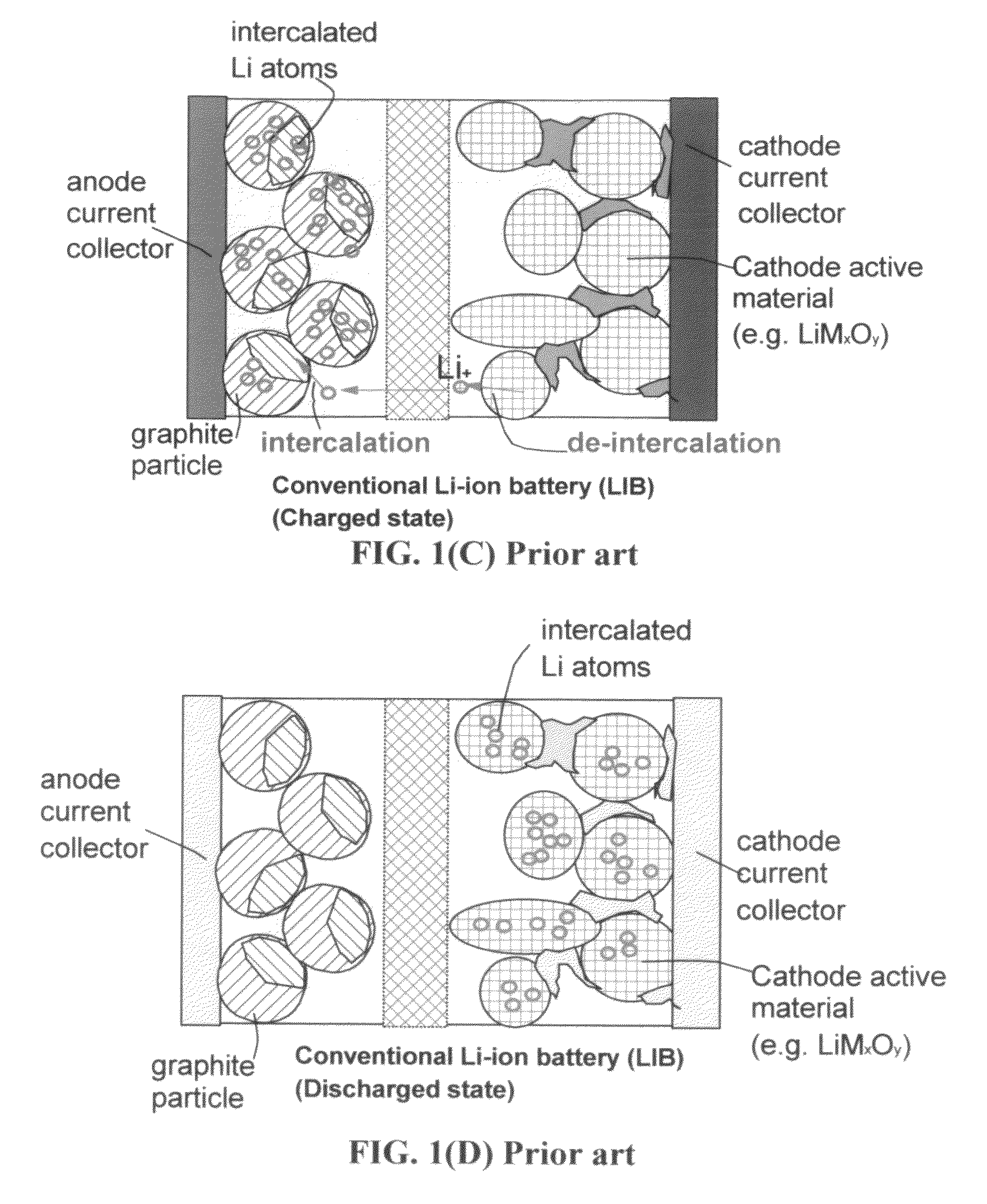
[0080]Because all the steps (lithium ionization, liquid phase diffusion, and surface trapping / adsorption / capturing) are fast and no solid-state diffusion is required, the whole process is very fast, enabling fast discharging of the SMC stack and a high power density. This is in stark contrast to the conventional lithium-ion battery (LIB) wherein lithium ions are required to diffuse into the bulk of a solid cathode particle (e.g., micron-sized lithium cobalt oxide) during discharge, which is a very slow process. During discharge of the LIB, these lithium ions have to come out of the bulk of graphite particles at the anode. Since liquid electrolyte only reaches the surfaces of these micron-scaled graphite particles (not in direct contact with the graphene planes inside the graphite particle), the lithium de-intercalation step also requires a slow solid-state diffusion.
[0081]In the above example, the discharge process continues until either the lithium foil is completely ionized or all the active sites on the cathode active materials in all constituent SMC cells are occupied by lithium atoms. During re-charge (FIG. 5C), lithium ions are released from the massive surfaces of the cathode active material at each cathode, diffuse through liquid electrolyte, and get captured by the surfaces of a nearby anode active material (e.g. simply get electrochemically deposited on a surface of a nano-structured anode material). Again, no solid-state diffusion is required and, hence, the whole process is very fast, requiring a short re-charge time.

Problems solved by technology

The load current drawn by power tools varies greatly, and often sharply, with time.
This creates enormous voltage ripple for the battery pack.
This is not ideal for most batteries, many of which are best suited to provide steady current levels.
This requires that additional complexity be designed into the protection circuit to prevent undesirable triggering of that circuit.
This circuitry tends to significantly degrade the effectiveness of the supercapacitor in these applications.
A combination of a battery pack and a supercapacitor device adds a considerably higher level of complexity, weight, and cost to the power system.
Moreover, both supercapacitors and batteries have their own intrinsic drawbacks that cannot be overcome even when they are combined or integrated into a power system.
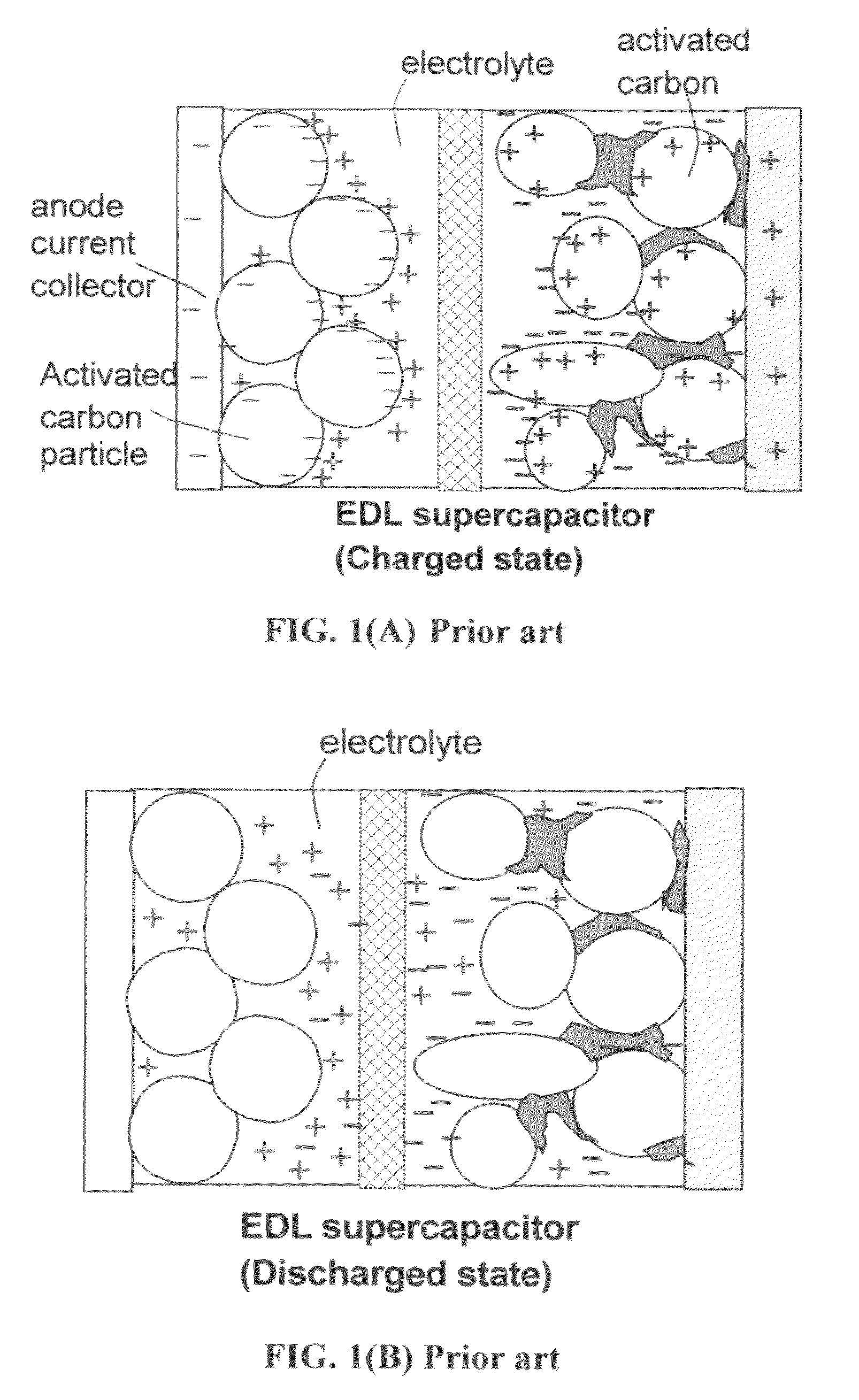
These concentrations are typically very low and are limited by the solubility of a salt in a solvent, resulting in a low energy density.
Despite the positive attributes of supercapacitors, there are several technological barriers to widespread implementation of supercapacitors for various industrial applications.
Although possessing a much higher energy density, lithium-ion batteries deliver a very low power density (typically 100-500 W / Kg), requiring typically hours for re-charge.
Conventional lithium-ion batteries also pose some safety concern.
In other words, these intercalation or solid-state diffusion processes require a long time to accomplish because solid-state diffusion (or diffusion inside a solid) is difficult and slow.
Furthermore, due to the need to undergo de-intercalation and intercalation at the anode, the power density of a LIC is not high (typically <15 kW / kg, which is comparable to or only slightly higher than those of an EDLC).
The above review of the prior art indicates that a battery has a higher energy density, but is incapable of delivering a high power (high currents or bursts of power) that a portable power tool needs.
A power source containing a battery alone is also not capable of being rapidly recharged (e.g., fully recharged in less than 30 minutes, preferably less than 10 minutes, and most preferably less than 1 minute).
A supercapacitor or LIC can deliver a higher power, but does not store much energy (the stored energy only lasts for a short duration of operating time) and, hence, cannot be a single power source alone to meet the energy / power needs of a portable power tool.
The lithium insertion or extraction procedures at both the cathode and the anode are very slow, resulting in a low power density and requiring a long re-charge time.b. When in a charged state, a LIC also stores lithium in the interior of graphite anode particles (FIG.
1(E)), thus requiring a long re-charge time as well.
During discharge, lithium ions must also diffuse out of the interior of graphite particles, thereby compromising the power density.
Hence, this is a totally new class of energy storage device that exhibits unparalleled and unprecedented combined performance of an exceptional power density, high energy density, long and stable cycle life, and wide operating temperature range.
One of the shortcomings of modern rechargeable batteries (e.g. nickel metal hydride and lithium-ion batteries) used to power portable devices is the poor power density (typically <0.5 kW / kg), resulting in a long battery recharge time and the inability to provide high currents or pulsed power.
Such a battery-supercapacitor configuration is bulky and heavy, which is a highly undesirable feature for a portable power tool.
However, this methodology results in significant underutilization of the capability of the supercapacitor system (typically less than 50% as voltage input variations are limited to 2:1 for many devices).
The addition of banks (either battery or supercapacitor) bring increased switching components / complexity, efficiency loss, increased weight and cost.

Method used


Image

  • Surface-mediated cell-driven power tools and methods of operating same
  • Surface-mediated cell-driven power tools and methods of operating same
  • Surface-mediated cell-driven power tools and methods of operating same

Examples


example

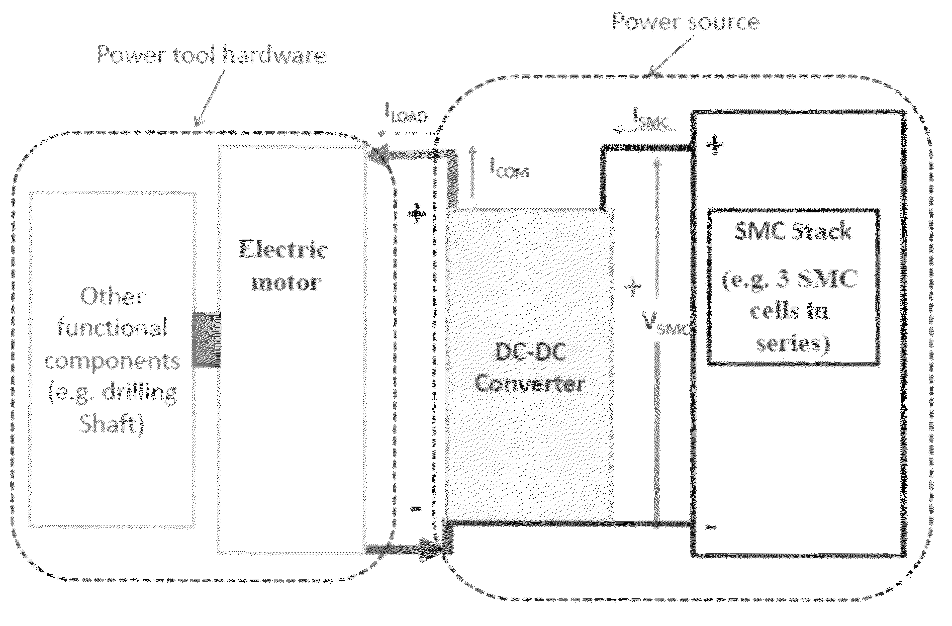
[0137]In order to evaluate the effectiveness of SMC-driven power tools, we have conducted an extensive and in-depth investigation. As one example, we purchased three NiCd batteries (each rated at 18 volts, 2000 mAh, 36 Wh, and rechargeable up to 1500 times) for a DeWalt DC212KA cordless hammer drill. One of the 3 batteries is for powering the drill alone, one for working with a stack of supercapacitor cells (connected in parallel with the supercapacitor stack), and one for working with a SMC stack. We constructed two stacks of SMC (each of 5 cells connected in series to provide a voltage rating of 18 volts), one to work alone (36 Wh) and the other (12 Wh) to work with one of the NiCd batteries for powering the drill. Thus, we had four power sources for driving the same type of drill: a NiCd battery alone, a NiCd-supercapacitor pair, a NiCd-SMC pair, and a SMC stack alone.

[0138]The drilling tool puts demands on the battery for high peak loads experienced during the onset of drilling....


PUM

PropertyMeasurementUnit
specific surface areaaaaaaaaaaa
voltageaaaaaaaaaa
diameteraaaaaaaaaa

Abstract

A portable power tool comprises an electric motor, actuator, or light-emitting hardware and a rechargeable power source connected to the electric motor, actuator, or light-emitting hardware, wherein the power source contains at least a surface-mediated cell (SMC). The power tools include, but are not limited to, impact driver, air compressor, alligator shear, angle grinder, band saw, belt sander, biscuit joiner, ceramic tile cutter tile saw, chainsaw, circular saw, concrete saw, cold saw, crusher, diamond blade, diamond tools, disc sander, drill, floor sander, grinding machine, heat gun, impact wrench, jackhammer, jointer, jigsaw, lathe, miter saw, nail gun, needle scaler, torque wrench, powder-actuated tools, power wrench, radial arm saw, random orbital sander, reciprocating saw, rotary reciprocating saw, rotary tool, sabre saw, sander, scroll saw, steel cut off saw, table saw, thickness planer, trimmer, wall chaser, wood router, or flashlight.

Description

[0001]This application claims the benefits of the following applications: (1) Aruna Zhamu, et al., “Surface-Mediated Lithium Ion-Exchanging Energy Storage Device,” U.S. patent application Ser. No. 13 / 199,450 (Aug. 30, 2011). (2) Aruna Zhamu, et al., “Partially Surface-Mediated Lithium Ion-Exchanging Cells and Method of Operating Same,” U.S. patent application Ser. No. 13 / 199,713 (Sep. 7, 2011). (3) Aruna Zhamu, et al., “Stacks of Internally Connected Surface-Mediated Cells and Methods of Operating Same,” U.S. patent application Ser. No. 13 / 374,321 (Dec. 21, 2011). (4) Aruna Zhamu, Guorong Chen, Qing Fang, Xiqing Wang, Yanbo Wang, and Bor Z. Jang, “Surface-Mediated Cell-Powered Vehicles and Methods of Operating Same,” U.S. patent application Ser. No. 13 / 374,894 (Jan. 23, 2012). (5) Aruna Zhamu, Guorong Chen, Qing Fang, Xiqing Wang, Yanbo Wang, and Bor Z. Jang, “Surface-Mediated Cells with High Power Density and High Energy Density,” U.S. patent application Ser. No. 13 / 385,105 (Feb. 3...

Claims


Application Information

Patent Timeline
Patent Type & Authority Patents(United States)
IPC IPC(8): B25F5/00H01M10/0525H01M16/00H01M4/00H01G11/50H02M3/158H01G11/06H01M14/00H01M12/00H01M6/50H01M10/46H01M4/133
CPCB25F5/00H01G11/50H01M10/0525H01M16/00H01G11/06H01M4/133H01M6/5033H01M10/465H01M12/005H01M14/00H01M2220/30H02M3/1582Y02B70/1483Y02E60/122Y02E60/13H01G11/36Y02B70/10Y02E60/10Y02P70/50
Inventor ZHAMU, ARUNACHEN, GUORONGXIONG, WEIJANG, BOR Z.WANG, YANBOFANG, QING
Owner GLOBAL GRAPHENE GRP INC
Why Eureka
Eureka Blog
Learn More