Separating method and equipment of low-carbon olefins beneficial to product recovery

A technology for recovery of low-carbon olefins and products, which is applied in the purification/separation of hydrocarbons, adsorption purification/separation, chemical instruments and methods, etc., and can solve the problems of driving, parking inconvenience, significant cooling cycle energy consumption, and increased separation energy consumption.

Active Publication Date: 2013-09-18
CHINA CONSTR IND & ENERGY ENG GRP CO LTD +1
View PDF38 Cites 22 Cited by
  • Summary
  • Abstract
  • Description
  • Claims
  • Application Information

AI Technical Summary

Problems solved by technology

[0021] To sum up, according to the characteristics of low-carbon olefin products from oxygenates, it is reasonable to avoid cryogenic separation; for the oil washing process, the main difference lies in the choice of absorbent and the sequence of the process arrangement, and its main disadvantages are : The amount of solvent circulation is large, and the energy consumption of the cooling cycle after solvent regeneration is significant, and part of the absorbent will be used as fuel gas with the top gas of the absorption tower, which reduces the use value of the absorbent itself. The process has certain restrictions on the selection of solvents, and sometimes requires Adding a desorption device and increasing the temperature of the demethanizer makes the loss of ethylene larger compared with the cryogenic process; for the improved "pre-cutting + oil absorption" and the process of adding an expander at the top of the demethanizer, both can reduce the amount of solvent circulation and Lower the tail gas temperature to increase the yield, but since the solvent comes from the inside of the system, the energy consumption is unavoidable in the solvent regeneration process of heating first and then cooling. , and it is necessary to establish a solvent cycle at a cold start, which brings inconvenience to driving and parking

Method used


Image

  • Separating method and equipment of low-carbon olefins beneficial to product recovery
  • Separating method and equipment of low-carbon olefins beneficial to product recovery

Examples


Embodiment 1

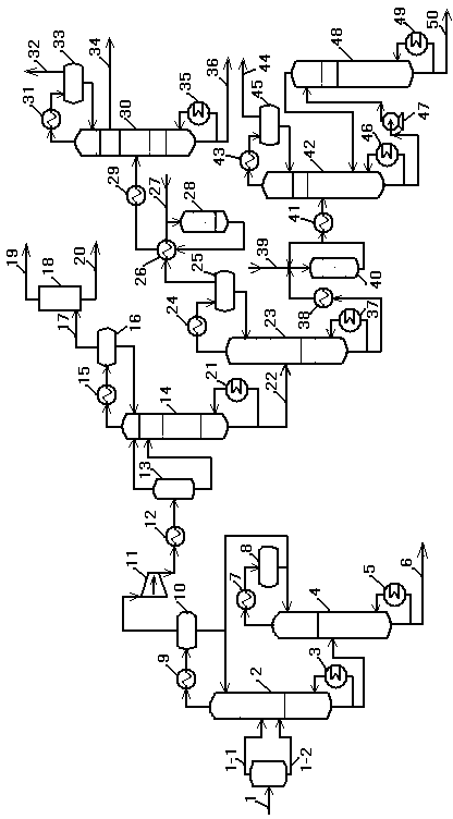
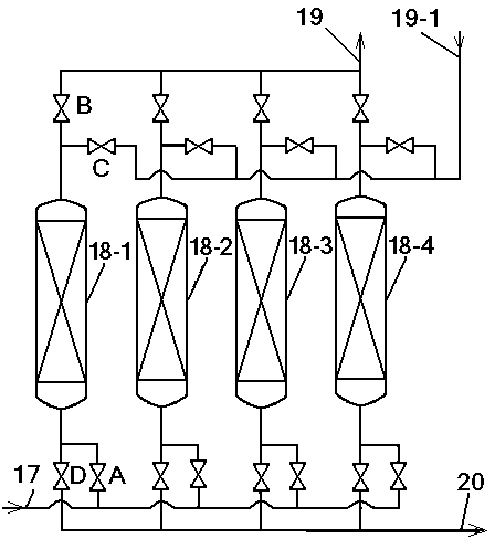
[0077] Such as figure 1 and figure 2 As shown, a low-carbon olefin separation method that is beneficial to product recovery, oxygenates are catalytically converted to produce a mixed gas of low-carbon olefins, and after the oxygenates and water are removed during pretreatment, in addition to ethylene and propylene, there is also Including one or more of hydrogen, oxygen, nitrogen, carbon monoxide, carbon dioxide, methane, ethane, acetylene, propane, cyclopropane, propyne and propadiene. The mixed material is compressed and heat-exchanged as a low-carbon olefin stream 1, which is divided into two phases of vapor and liquid, wherein the vapor phase passes through the pipeline 1-1, and the liquid phase enters the high-pressure depropanizer 2 through the pipeline 1-2, and the high-pressure depropanizer The tower bottom reboiler 3 is heated by steam so that the tower bottom product 6 enters the low-pressure depropanizer 4 for separation of C3 and C4. The butane tower system is ...

Embodiment 2

[0090] The difference between Example 2 and Example 1 is that the numerical parameters involved are: the operating pressure at the top of the high-pressure depropanizer is 1.8MPa, and the bottom temperature of the high-pressure depropanizer is 100°C; The operating pressure at the top of the tower is 0.5MPa, and the temperature at the bottom of the low-pressure depropanizer is 100°C; the operating pressure at the top of the demethanizer is 3.5MPa; the temperature at the top of the demethanizer is -45°C; the temperature at the top of the demethanizer is -45°C; The temperature at the bottom of the tower is -5°C, and the tower kettle is heated by circulating water; the pressure swing adsorbent is modified activated carbon loaded with copper, the adsorption pressure is 3.5MPa, and the adsorption temperature is -5°C; the deethanizer The operating pressure at the top of the tower is 2.0MPa; the temperature of the bottom of the deethanizer tower is 20°C; the operating pressure at the t...

Embodiment 3

[0092] The difference between embodiment 3 and embodiment 1 is that the numerical parameters involved are: the operating pressure at the top of the high-pressure depropanizer is 3.8MPa, and the temperature at the bottom of the high-pressure depropanizer is 20°C; The operating pressure at the top of the tower is 1.5MPa, and the temperature at the bottom of the low-pressure depropanizer is 20°C; the operating pressure at the top of the demethanizer is 4.0MPa; the temperature at the top of the demethanizer is -43°C; the temperature at the top of the demethanizer is -43°C; The temperature at the bottom of the tower is 45°C, and the tower kettle is heated by circulating water; the pressure swing adsorbent is modified activated carbon loaded with copper, the adsorption pressure is 3.0MPa, and the adsorption temperature is 50°C; the top of the deethanizer is The operating pressure is 3.3MPa, and the temperature of the deethanizer tower is 100°C; the operating pressure at the top of th...


PUM

PropertyMeasurementUnit
pressureaaaaaaaaaa
adsorption temperatureaaaaaaaaaa
pressureaaaaaaaaaa

Abstract

The invention discloses a separating method and corresponding equipment of low-carbon olefins beneficial to product recovery. The separating method comprises the steps of: pretreating and delivering oxygenated chemical-converted low-carbon olefin flow into a depropanization system, cooling and delivering top products of the depropanization system into a demethanizing tower, cooling the top of the demethanizing tower only with a propylene refrigerant, delivering vapor phase at the tower top into a pressure swing adsorption device for recovering ethylene, returning the recovered crude ethylene gas back before a segment of compressor to be mixed with low-carbon olefin reaction gas flow, so that a copious cooling cold box and an ethylene refrigeration compressor are omitted, and the fixed investment and energy consumption can be reduced. Compared with the prior art, the separating method and corresponding equipment have the advantages of being low in separating energy consumption, high in material recovery rate, small in influence on the following ethylene and propylene separation, and the like.

Description

technical field [0001] The invention belongs to the technical field of separation and purification of low-carbon olefins, and relates to a method of producing low-carbon olefins mainly using oxygen-containing compounds (mainly methanol, ethanol, dimethyl ether, C4-C10 alcohol compounds or their mixtures, etc.) as raw materials. In the process of logistics (mainly ethylene and propylene), the separation method and equipment of the product low-carbon olefin gas. Background technique [0002] The traditional source of ethylene and propylene is mainly steam cracking of petroleum hydrocarbons, and its raw material is mainly naphtha. However, the shortage of petroleum resources in my country is the main reason restricting the development of my country's ethylene industry. With the increasingly tight supply of oil, the production of low-carbon olefins from oxygenated compounds (OTO process) has become a research hotspot. A new process route for basic organic chemical raw materials...

Claims


Application Information

Patent Timeline
Patent Type & Authority Applications(China)
IPC IPC(8): C07C11/04C07C11/06C07C7/00C07C7/12
Inventor 相咸高梅华李本勇董巍巍张少石余雷
Owner CHINA CONSTR IND & ENERGY ENG GRP CO LTD
Why Eureka
Try Eureka