Method and system for removing sulfur dioxide in flue gas

A sulfur dioxide and flue gas technology, applied in chemical instruments and methods, separation methods, preparation of alkali metal sulfites, etc., can solve the problems of high operating cost and low desulfurization efficiency, and achieve low operating cost, long contact time, The effect of reducing operating costs

Inactive Publication Date: 2014-08-13
株洲三特环保节能股份有限公司
View PDF6 Cites 8 Cited by
  • Summary
  • Abstract
  • Description
  • Claims
  • Application Information

AI Technical Summary

Problems solved by technology

[0003] The present invention solves the technical problems of low desulfurization efficiency and high operating cost in existing methods for removing sulfur dioxide in flue gas, and provides a method and system for removing sulfur dioxide in flue gas with high desulfurization efficiency and low cost

Method used


Image

  • Method and system for removing sulfur dioxide in flue gas

Examples


Embodiment 1

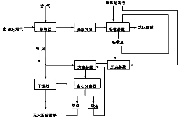
[0059] 1), the pending SO 2 The concentration is 35000mg / Nm 3 1. Flue gas from a zinc smelting rotary kiln at a temperature of 280°C and air at normal temperature are respectively passed into heat exchanger 1 for heat exchange, so that the temperature of the flue gas is reduced to 160°C, and at the same time, the air is heated into hot air at 110°C;

[0060] 2) The sulfur-containing flue gas after heat exchange is sent to the washing tower for washing to remove the soot and SO in the flue gas 3 and other impurities, and further reduce the flue gas temperature to 60°C;

[0061] 3) The sulfur-containing flue gas after purification and cooling is successively sent to the tubular rotary shear flow absorber and the spray absorption tower to be mixed with 35% sodium carbonate, 15% sodium sulfite, and 5% sodium bisulfite Solution reverse contact reaction, sulfur-containing flue gas is absorbed to form clean flue gas emission, and generates Na 2 SO 3 and NaHSO 3 the m...

Embodiment 2

[0067] 1) The SO2 concentration to be treated is 20000 mg / Nm 3 1. Flue gas from a zinc smelting volatilization kiln at a temperature of 250°C and air at normal temperature are respectively passed into heat exchanger 1 for heat exchange, so that the temperature of the flue gas is reduced to 150°C, and at the same time, the air is heated into hot air at 110°C;

[0068] 2) The sulfur-containing flue gas after heat exchange is sent to the washing tower for washing to remove the soot and SO in the flue gas 3 and other impurities, and further reduce the flue gas temperature to 70°C;

[0069]3) The sulfur-containing flue gas after purification and cooling is successively sent to the tubular rotary shear flow absorber and the spray absorption tower to be mixed with 40% sodium carbonate, 18% sodium sulfite, and 8% sodium bisulfite Solution reverse contact reaction, sulfur-containing flue gas is absorbed to form clean flue gas emission, and generates Na 2 SO 3 and NaHSO 3 the...

Embodiment 3

[0075] 1) will be treated containing SO 2 Concentration 40000 mg / Nm 3 1. Flue gas from a zinc smelting volatilization kiln at a temperature of 250°C and air at normal temperature are respectively passed into heat exchanger 1 for heat exchange, so that the temperature of the flue gas is reduced to 180°C, and at the same time, the air is heated into hot air at 120°C;

[0076] 2) The sulfur-containing flue gas after heat exchange is sent to the washing tower for washing to remove the soot and SO in the flue gas 3 and other impurities, and further reduce the flue gas temperature to 65°C;

[0077] 3) The sulfur-containing flue gas after purification and cooling is successively sent to the tubular rotary shear flow absorber and the spray absorption tower to be mixed with 40% sodium carbonate, 20% sodium sulfite, and 10% sodium bisulfite Solution reverse contact reaction, sulfur-containing flue gas is absorbed to form clean flue gas emission, and generates Na 2 SO 3 and...


PUM


Abstract

The invention provides a method and system for removing sulfur dioxide in flue gas. The method comprises the following steps: absorbing and converting sulfur dioxide in flue gas into a mixed solution of Na2SO3 and NaHSO3 by adopting an absorption solution of sodium carbonate, sodium sulfite and sodium hydrogen sulfite, and carrying out a neutralization reaction between the mixed solution and a sodium carbonate solution, so that NaHSO3 in the mixed absorption solution is converted into Na2SO3 and Na2SO3 is crystallized and separated out; and after concentrating the crystallization solution in a concentration tower through hot air generated by a heat exchanger, centrifugally separating a mother solution, continuing concentration after returning the concentration tower, and performing hot air drying on crystals to form a desulfurization byproduct, namely anhydrous sodium sulfite. The method is short in process follow, high in desulfurization efficiency, low in energy consumption and low in operating cost; flue gas absorption, absorption solution neutralization and crystallization, hot air concentration and drying systems are in a totally-closed cycle operation mode, and secondary pollution is avoided; moreover, the method is applicable to removal and recycling of sulfur dioxide in flue gas of various industrial furnaces and coal-fired boilers in industries such as metallurgy, steel and thermal power.

Description

technical field [0001] The invention belongs to the technical field of resource and environment protection, and in particular relates to a method and system for removing sulfur dioxide in flue gas. Background technique [0002] Low concentration of sulfur dioxide (SO 2 ) flue gas mainly comes from thermal processes such as the combustion of fossil fuels, roasting of sulfur-containing ores, smelting, and chemical production. harm. In the prior art, flue gas desulfurization usually adopts wet desulfurization method, which mainly uses various alkaline absorbents or adsorbents to capture sulfur dioxide in flue gas and convert it into relatively stable and easily mechanically separated sulfur compounds or simple substances. sulfur, so as to achieve the purpose of desulfurization. At present, the main flue gas desulfurization technologies in industrialization are: 1. Ordinary wet limestone-gypsum method, which uses lime or limestone slurry to absorb SO in flue gas 2 , to gene...

Claims


Application Information

Patent Timeline
Patent Type & Authority Applications(China)
IPC IPC(8): B01D53/78B01D53/50C01D5/14
Inventor 李剑胜
Owner 株洲三特环保节能股份有限公司
Why Eureka
Try Eureka