
Method for modifying current collector of lithium ion battery with conductive metal ceramic

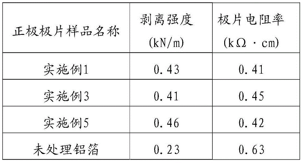
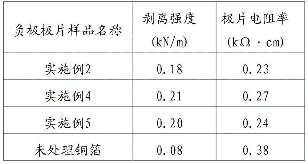
A lithium-ion battery and conductive metal technology, which is applied in battery electrodes, secondary batteries, electrode carriers/collectors, etc., can solve the problems of weak bonding between active materials and current collectors, increased electrode resistance, and reduced battery performance. , to achieve the effect of increasing cycle life and rate performance, reducing contact internal resistance, and increasing peel strength

Active Publication Date: 2014-11-19
HEFEI GUOXUAN HIGH TECH POWER ENERGY
View PDF5 Cites 10 Cited by
  • Summary
  • Abstract
  • Description
  • Claims
  • Application Information

AI Technical Summary

Problems solved by technology

[0004] The traditional lithium battery pole piece preparation process is to uniformly coat the active material on the surface of aluminum foil (positive current collector) or copper foil (negative current collector) through a binder, but the amount of binder has contradictory effects on battery performance. Influence, when the amount is too small, the active material and the current collector will not be firmly bonded, and swelling or powder loss will easily occur during processing and charging and discharging, resulting in a decrease in the life of the battery cycle performance; if the amount of the adhesive is too high, it will increase the electrode Resistance, resulting in excessive internal resistance of the battery, significantly reducing battery performance
[0005] At the same time, the current collector is also faced with the challenge of corrosion by electrolyte decomposition products during use. The metal ions formed by corrosion will not only attack the active material and cause an increase in internal resistance, but also dissolve in the electrolyte and cause the self-discharge rate to slow down. Li will be reduced and deposited on the surface of the negative electrode + , these will cause serious capacity fading, resulting in reduced battery cycle life

Method used


Image

  • Method for modifying current collector of lithium ion battery with conductive metal ceramic
  • Method for modifying current collector of lithium ion battery with conductive metal ceramic

Examples


Embodiment 1

[0025] S1: Preparation of conductive cermet slurry: 0.1% nickel powder (mass ratio) is added to tungsten carbide powder, 1% polyvinyl alcohol (mass ratio) is added as a binder, water is used as a dispersant, and a planetary ball mill is used at 400r 4h mixing at a rotation speed of / min to obtain conductive cermet slurry;

[0026] S2: Preparation of conductive cermet powder: The slurry is pumped into the spray drying tower by a peristaltic pump to prepare conductive cermet powder with a particle size of about 4μm. The preparation of conductive cermet powder is achieved by controlling the following parameters of the spray drying tower: air intake The temperature is 250℃, the outlet temperature is 120℃, and the feed rate is 25mL / min;

[0027] S3: Lithium battery current collector metal surface cleaning treatment: ultrasonically clean the lithium battery positive electrode (aluminum foil) current collector metal with acetone, ethanol and deionized water respectively;

[0028] S4: Plasm...

Embodiment 2

[0030] S1: Preparation of conductive cermet slurry: 0.1% aluminum powder (mass ratio) is added to titanium carbide powder, 1% polytetrafluoroethylene (mass ratio) is added as a binder, water is used as a dispersant, and a planetary ball mill is used to 400r / min rotating speed mixed for 4h to obtain conductive metal ceramic slurry;

[0031] S2: Preparation of conductive cermet powder: the slurry is pumped into the spray drying tower by a peristaltic pump to prepare conductive cermet powder with a particle size of about 4μm, which is achieved by controlling the following parameters: inlet temperature 250°C, outlet temperature 120°C, Feed volume 25mL / min;

[0032] S3: Lithium battery current collector metal surface cleaning treatment: ultrasonically clean the lithium battery negative electrode (copper foil) current collector metal with acetone, ethanol and deionized water respectively;

[0033] S4: Plasma spraying: Using atmospheric plasma spraying technology to evenly spray the cermet...

Embodiment 3

[0035] S1: Preparation of conductive cermet slurry: 2% iron powder (mass ratio) is added to the chromium carbide powder, 2% polyacrylic acid (mass ratio) is added as the binder, water is used as the dispersant, and the planetary ball mill is used at 400r / Mix at min speed for 4 hours to obtain conductive cermet slurry;

[0036] The slurry is pumped into the spray drying tower through a peristaltic pump to prepare conductive cermet powder with a particle size of about 7μm. This is achieved by controlling the following parameters: inlet temperature 250°C, outlet temperature 120°C, and feed volume 25mL / min;

[0037] S2: Preparation of conductive cermet powder: the slurry is pumped into the spray drying tower by a peristaltic pump to prepare conductive cermet powder with a particle size of about 4μm, which is achieved by controlling the following parameters: inlet temperature 250°C, outlet temperature 120°C, Feed volume 25mL / min;

[0038] S3: Lithium battery current collector metal surf...


PUM

PropertyMeasurementUnit
Particle sizeaaaaaaaaaa
Thicknessaaaaaaaaaa
Thicknessaaaaaaaaaa

Abstract

The invention discloses a method for modifying a current collector of a lithium ion battery with a conductive metal ceramic. The method comprises the following steps: S1, mixing conductive metal ceramic powder, a film-forming assistant and a bonder as raw materials with water as a dispersant to obtain conductive metal ceramic slurry A; S2, performing spray-drying on the slurry A to prepare conductive metal ceramic powder B with uniform particle size; S3, ultrasonically cleaning the positive or negative current collector by acetone, ethanol and de-ionized water respectively; S4, uniformly spraying the conductive metal ceramic powder B as a raw material onto the surface of the cleaned positive or negative current collector subjected to cleaning in the step S3 by an atmospheric plasma spraying technology to form a conductive metal ceramic coating C on the surface of the positive or negative current collector.

Description

Technical field [0001] The invention relates to the technical field of lithium ion battery manufacturing, in particular to a method for modifying a lithium ion battery current collector with conductive metal ceramics. Background technique [0002] As a new generation of green rechargeable power source, lithium-ion batteries have the advantages of high energy density, high working voltage, and good cycle performance. It is gradually replacing nickel / hydrogen, nickel / cadmium and other batteries in electric vehicles, hybrid vehicles, power tools, 3C products, and energy storage. It has a wide range of application prospects. It can also be used for modern military equipment such as communication systems, aerospace, etc. Provide a reliable secondary power supply. Therefore, the development of lithium batteries with good adaptability to the environment, long service life, high energy density, and good safety performance has become the focus of research. [0003] As an important part of...

Claims


Application Information

Patent Timeline
IPC IPC(8): H01M4/66
CPCH01M4/664H01M10/0525Y02E60/10
Inventor 汪涛彭文
Owner HEFEI GUOXUAN HIGH TECH POWER ENERGY
Learn More