System and method for generating power by means of sludge

A sludge and inlet technology, applied in the field of power generation systems using sludge, can solve the problems of difficult industrial application, high maintenance frequency, and high operating costs, and achieve easy industrialization and scale, high resource utilization level, and increase economic benefits Effect

Pending Publication Date: 2017-03-08
SHENWU TECH GRP CO LTD
View PDF0 Cites 2 Cited by
  • Summary
  • Abstract
  • Description
  • Claims
  • Application Information

AI Technical Summary

Problems solved by technology

[0005] The purpose of the present invention is to solve the problems of large pyrolysis oil output, serious clogging, high degree of corrosion, high maintenance frequency and high treatment cost in the sludge pyrolysis process, as well as the small processing scale a

Method used


Image

  • System and method for generating power by means of sludge
  • System and method for generating power by means of sludge
  • System and method for generating power by means of sludge

Examples


Embodiment 1

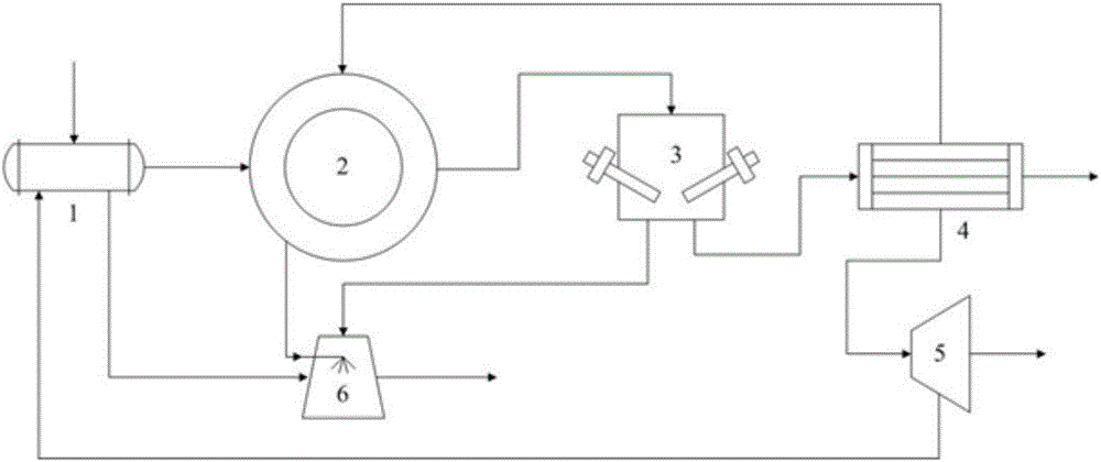
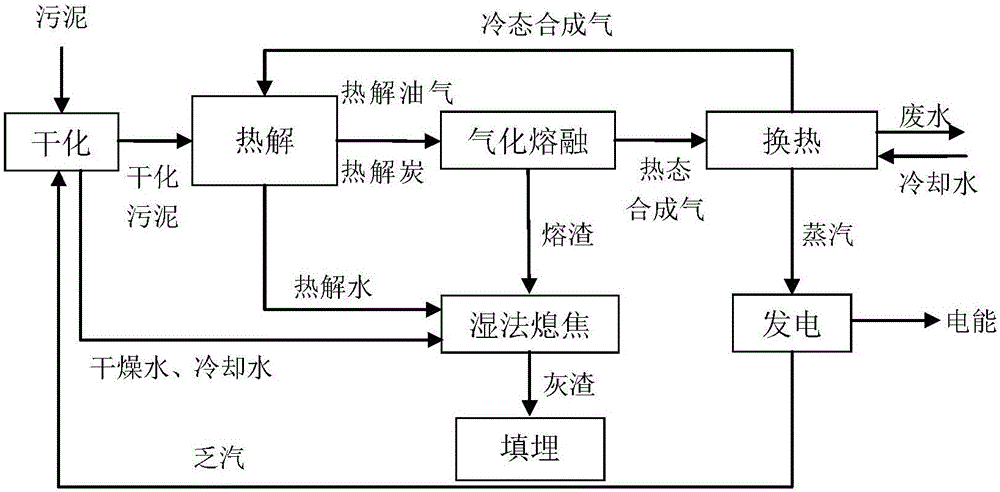
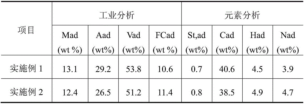
[0068] This embodiment adopts figure 1 The system shown and figure 2 The process route shown uses sludge for power generation. The sludge used is the sludge from a certain urban sewage treatment plant. Its industrial analysis and elemental analysis are shown in Table 1. The specific treatment process is as follows:

[0069] The sludge with a moisture content of 88% is sent to the drying device 1 to produce 48% dry water, and the sludge with a moisture content of 40% is sent to the regenerative rotary bed 2, and the regenerative radiant tube in the drying area The temperature of the pyrolysis zone is 400°C and the temperature of the regenerative radiant tube is 600°C. The sludge undergoes drying and pyrolysis successively in the regenerative rotary bed 2, and the finally obtained pyrolysis water flows out from the pyrolysis water outlet, and enters the coke quenching device 6 together with the drying water and cooling water produced by drying , the pyrolysis oil gas is disc...

Embodiment 2

[0072] This embodiment adopts figure 1 The system shown and figure 2 The process route shown uses sludge for power generation. The sludge used is the sludge from a certain urban sewage treatment plant. Its industrial analysis and elemental analysis are shown in Table 1. The specific treatment process is as follows:

[0073] The sludge with a moisture content of 85% is sent to the drying device 1 to produce 45% dry water, and the sludge with a moisture content of 40% is sent to the regenerative rotary bed 2, and the regenerative radiant tube in the drying area The temperature of the pyrolysis zone is 500°C and the temperature of the regenerative radiant tube is 900°C. The sludge undergoes drying and pyrolysis successively in the regenerative rotary bed 2, and the finally obtained pyrolysis water flows out from the pyrolysis water outlet, and enters the coke quenching device 6 together with the drying water and cooling water produced by drying , the pyrolysis oil gas is disc...


PUM


Abstract

The invention discloses a system and a method for generating power by means of sludge. The system comprises a drying device, a heat accumulating type revolving bed, a gasification and melting reaction chamber, a heat exchange device and a power generation device, wherein a sludge inlet, a dried sludge outlet, a drying water outlet, a steam inlet and a cooling water outlet are formed in the drying device; a raw material inlet, a pyrolytic water outlet, a pyrolytic oil gas outlet and a pyrolytic carbon outlet are formed in the heat accumulating type revolving bed, and the raw material inlet is connected with the dried sludge outlet; a pyrolytic oil gas inlet, a pyrolytic carbon inlet, a thermal-state synthesis gas outlet and a slag outlet are formed in the gasification and melting reaction chamber, the pyrolytic oil gas inlet is connected with the pyrolytic oil gas outlet, and the pyrolytic carbon inlet is connected with the pyrolytic carbon outlet; a thermal-state synthesis gas inlet, a cool-state synthesis gas outlet, a waste water outlet, a cooling water inlet and a steam outlet are formed in the heat exchange device, and the thermal-state synthesis gas inlet is connected with the thermal-state synthesis gas outlet; a steam inlet, a steam exhaust outlet and an electric quantity outlet end are formed in the power generation device, and the steam inlet is connected with the steam outlet. With the adoption of the system and the method, harmlessness, reduction and recycling of sludge are realized.

Description

technical field [0001] The invention belongs to the field of solid waste resource treatment, and in particular relates to a system and method for generating electricity by utilizing sludge. Background technique [0002] With the improvement of environmental protection level. The amount of urban sewage treatment has been increasing year after year, and as a by-product of urban sewage treatment, the annual production rate of urban sludge has also increased sharply. Sludge is a flocculent mud particle with a high water content (85%-95%), which contains a large amount of heavy metals, nitrogen and phosphorus, pathogenic bacteria, viruses and toxic organic substances. If it is discharged into the water body randomly, it will cause the deterioration of the water body and affect the survival of aquatic organisms; if it is used in agriculture, it will pollute the soil, cause crop diseases, and even endanger human health. Therefore, how to effectively and harmlessly dispose of muni...

Claims


Application Information

Patent Timeline
IPC IPC(8): C02F11/00C02F11/12C02F11/10C10J3/58C10J3/72
CPCY02W10/40C02F11/00C02F11/10C02F11/12C02F2303/06C02F2303/10C10J3/58C10J3/72C10J2300/0909C10J2300/0923C10J2300/1238C10J2300/1671C10J2300/1687C10J2300/1823
Inventor 刘璐张安强任浩华蔡先明赵月晶肖磊吴道洪
Owner SHENWU TECH GRP CO LTD
Why Eureka
Try Eureka