Vacuum film-coating method through combined magnetic field and compounding of lining special-shaped pipe and porous baffle
A porous baffle and vacuum coating technology, applied in vacuum evaporation coating, sputtering coating, ion implantation coating, etc., can solve the problems of film component pollution, large particle defects, low film deposition efficiency, etc., to ensure uniform performance, and the effect of improving utilization efficiency
- Summary
- Abstract
- Description
- Claims
- Application Information
AI Technical Summary
Problems solved by technology
Method used
Image
Examples
specific Embodiment approach 1
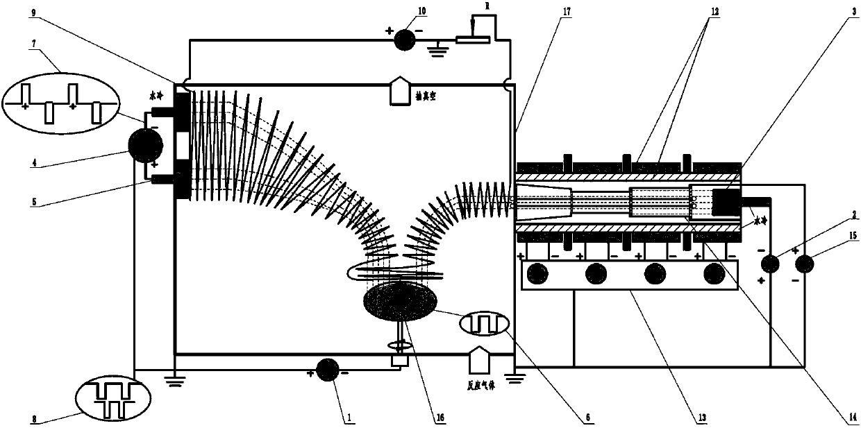
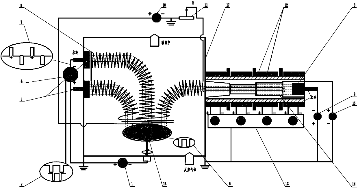
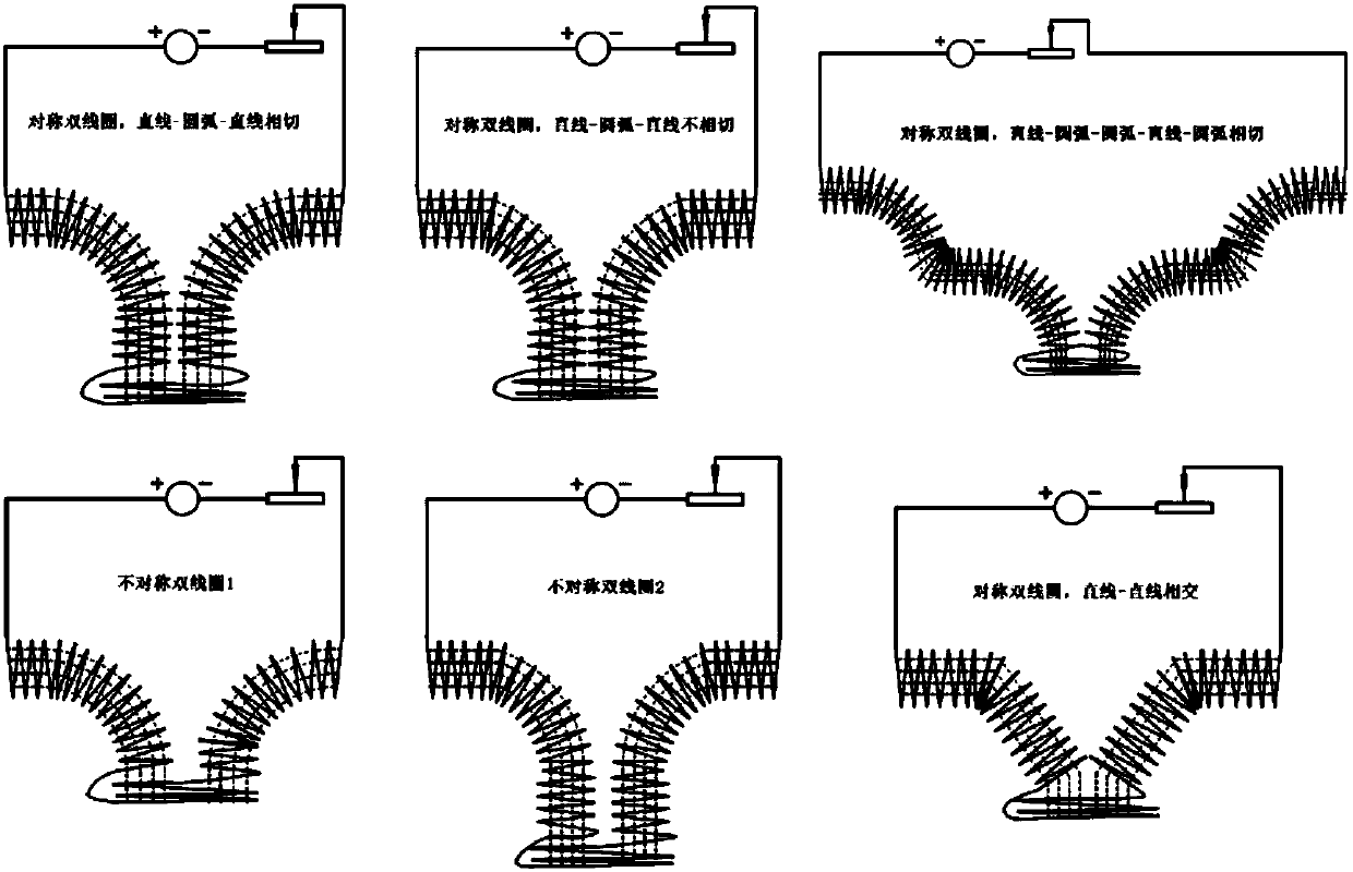
[0025] Specific implementation mode one: the following combination Figure 1-6Describe this embodiment, the device used in this embodiment is a combination of magnetic field and lined special-shaped tube and porous baffle composite vacuum coating method includes bias power supply (1), arc power supply (2), arc ion plating target source (3 ), twin target high power pulse magnetron sputtering power supply (4), twin target high power pulse magnetron sputtering target source (5), bias power waveform oscilloscope (6), twin target high power pulse magnetron sputtering power supply Waveform oscilloscope (7), waveform synchronous matching device (8), movable coil device (9), movable coil device power supply (10), rheostat device (11), multi-level magnetic field device (12), multi-level magnetic field device power supply (13 ), lined bias conical tube, stepped tube and porous baffle combined device (14), lined bias power supply (15), sample stage (16) and vacuum chamber (17);
[0026]...
specific Embodiment approach 2
[0044] Embodiment 2: The difference between this embodiment and Embodiment 1 is that a combined magnetic field is connected with a vacuum coating method in which the lined special-shaped tube is combined with a porous baffle, the arc power supply (2) is turned on, and the multi-stage magnetic field power supply is turned on. (5) Adjust the multi-level magnetic field device (12), turn on the lining bias power supply (15) adjust the bias voltage of the lining bias conical tube, stepped tube and porous baffle combination device (14), and turn on the movable coil device power supply (10) Adjust the movable coil device (9), adjust the output resistance of the rheostat device (10), and control the bias power supply (1) and twin target high-power pulse magnetron sputtering power supply (4) by the waveform synchronous matching device (8) At the same time, the period of the output pulse of the twin target high-power pulse magnetron sputtering power supply (4) is an integer multiple of t...
specific Embodiment approach 3
[0045]Embodiment 3: The difference between this embodiment and Embodiment 1 is that a combined magnetic field is connected with a vacuum coating method in which a special-shaped tube lined with a porous baffle is combined, the arc power supply (2) is turned on, and the multi-stage magnetic field power supply is turned on. (5) Adjust the multi-stage magnetic field device (12), turn on the lining bias power supply (15), adjust the bias voltage of the lining bias conical tube, stepped tube and porous baffle assembly (14), and turn on the movable coil device power supply (10) Adjust the movable coil device (9), adjust the output resistance of the rheostat device (10), and control the bias power supply (1) and twin target high-power pulse magnetron sputtering power supply (4) by the waveform synchronous matching device (8) Simultaneously turned on, twin target high-power pulse magnetron sputtering power supply (4) outputs high-power pulses and the bias pulse waveform output by bias ...
PUM
 Abstract
Description
Claims
Application Information
 - R&D
- Intellectual Property
- Life Sciences
- Materials
- Tech Scout
- Unparalleled Data Quality
- Higher Quality Content
- 60% Fewer Hallucinations
Browse by: Latest US Patents, China's latest patents, Technical Efficacy Thesaurus, Application Domain, Technology Topic, Popular Technical Reports.
© 2025 PatSnap. All rights reserved.Legal|Privacy policy|Modern Slavery Act Transparency Statement|Sitemap|About US| Contact US: help@patsnap.com


