Radio-frequency inductive coupling linear ion source

A radio frequency inductive coupling, linear ion source technology, applied in the field of ion beam control, can solve the problems of restricting ion beam spot, uneven plasma density distribution, reducing coupling efficiency and plasma density distribution uniformity, etc.

Pending Publication Date: 2020-07-07
中核同创(成都)科技有限公司
View PDF0 Cites 7 Cited by
  • Summary
  • Abstract
  • Description
  • Claims
  • Application Information

AI Technical Summary

Problems solved by technology

On the one hand, because the beam spot increases, the area of ​​the RF antenna and the dielectric coupling window must also increase. The larger the antenna length, the larger the inductance, the larger the distributed capacitance and the RF voltage at both ends of the antenna, and the high voltage at both ends of the antenna will cause The capacitive coupling between the RF antenna and the plasma load and the discharge of the RF antenna cause problems such as uneven distribution of plasma density, unstable impedance matching between the RF power supply and the plasma load, and low RF coupling efficiency. The antenna also makes the plasma density more non-uniform due to the standing wave effect
At the same time, due to the strength requirements of the coupling window isolation vacuum structure, the larger the dielectric coupling window, the thic

Method used


Image

  • Radio-frequency inductive coupling linear ion source
  • Radio-frequency inductive coupling linear ion source
  • Radio-frequency inductive coupling linear ion source

Examples


Embodiment 1

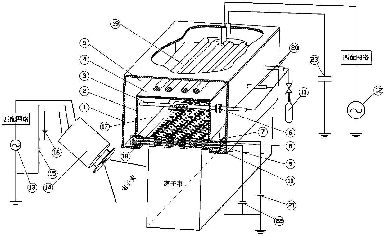
[0031] like figure 1As shown, a radio-frequency inductively coupled linear ion source includes: an ion source shielding case 1, a radio-frequency coupling antenna 19, a dielectric coupling window 4 for transmitting radio-frequency power and isolating the discharge chamber and the antenna chamber, and a housing for accommodating the discharge plasma The side wall of the plasma discharge chamber 2, the multi-grid ion beam extraction system 7 for extracting ion beams from the plasma discharge chamber, the radio frequency neutralizer for providing initial electrons into the discharge chamber and neutralizing electrons to the ion beam and the substrate Ander 14. Further, it also includes the ion beam screen grid power supply 21, the acceleration grid power supply 22, the radio frequency power generator 12 that provides radio frequency power to the ion source screen grid 8, the acceleration grid 9 and the ground grid 10, and the bias voltage and matching network, a gas supply syste...

Embodiment 2

[0038] like image 3 As shown, on the basis of Embodiment 1, a "comb" Faraday electrostatic shield 24 is provided above the dielectric coupling window 4 of the plasma discharge chamber 17 to reduce the capacitive coupling between the antenna and the discharge plasma and improve the discharge efficiency , to reduce plasma etching and contamination of the coupling window. In order to further improve the density and uniformity of the radio frequency discharge plasma, a magnetic steel 25 is installed between the side wall 2 of the plasma discharge chamber and the shielding shell 1 of the ion source to generate a confinement plasma cusp field.

Embodiment 3

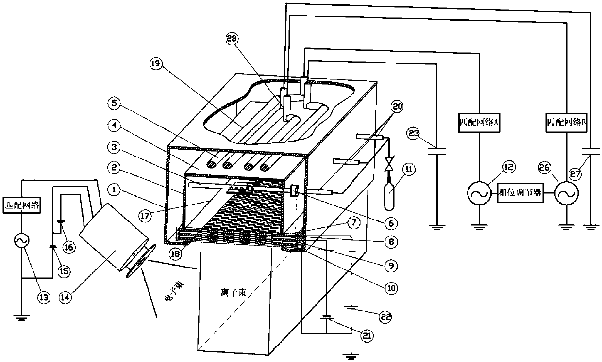
[0040] like figure 1 As shown, on the basis of Embodiment 1, the radio frequency coupling antenna is an antenna group composed of radio frequency antenna 19 and radio frequency antenna 28, and radio frequency energy passes through radio frequency power supply 12, radio frequency power supply A26 and matching network A, matching network B, DC blocking capacitor A23 and the DC blocking capacitor B27 feed energy into the RF coupling antenna 19 and the RF coupling antenna A28 respectively. The RF voltage and power of the RF power sources 12 and 26 can be adjusted independently, and their phase can be controlled by a phase regulator. The uniformity of the discharge plasma can be further improved by controlling the phase and power of the RF power sources 12 and 26 .


PUM


Abstract

The invention belongs to the technical field of ion beam control, and particularly relates to a radio-frequency inductive coupling linear ion source. The radio-frequency inductive coupling linear ionsource comprises an ion source shielding shell, a radio frequency coupling antenna, a dielectric coupling window used for transmitting radio-frequency power and isolating a discharge chamber from an antenna chamber, a plasma discharge chamber side wall used for accommodating discharge plasmas, a multi-grid ion beam extraction system used for extracting ion beams from the plasma discharge chamber,and a radio-frequency neutralizer used for providing initial electrons into the discharge chamber and providing neutralized electrons into the ion beams and a base material. The radio-frequency inductive coupling linear ion source can generate high-uniformity large-area narrow and long linear ion beams in a large size range, and is suitable for processes of ion beam cleaning, etching, thin film deposition and the like of large-area base materials.

Description

technical field [0001] The invention belongs to the technical field of ion beam control, and in particular relates to a radio frequency induction coupled linear ion source. Background technique [0002] The radio frequency inductively coupled ion source uses radio frequency inductive coupling to generate plasma, has no built-in electrodes, and has the characteristics of no pollution and high plasma density. It is the most widely used ion source in the field of microfabrication. According to the structural form of the radio frequency antenna, there are mainly two types - spiral tube type and coil incense type. The toroidal RF inductively coupled ion source adopts a spring-shaped helical antenna, and the antenna is helically coiled outside the dielectric discharge chamber. Due to the skin effect of RF power transmission, the electrons in the discharge chamber are accelerated by the inductively coupled electric field along the direction parallel to the inner wall of the discha...

Claims


Application Information

Patent Timeline
IPC IPC(8): H05H1/03H05H1/10H05H1/46
CPCH05H1/03H05H1/10H05H1/46H05H1/4645H05H2242/20
Inventor 陈庆川聂军伟黄琪石连天
Owner 中核同创(成都)科技有限公司
Why Eureka
Try Eureka