Irradiation-resistant erbium-doped optical fiber for space and preparation method of irradiation-resistant erbium-doped optical fiber

An erbium-doped optical fiber, radiation-resistant technology, applied in cladding optical fiber, laser, optical waveguide light guide, etc., can solve problems such as failure and optical fiber performance degradation, and achieve the effect of reducing loss, reducing stress loss, and suppressing easy dehydrogenation

Active Publication Date: 2020-08-18
XI'AN INST OF OPTICS & FINE MECHANICS - CHINESE ACAD OF SCI
View PDF14 Cites 4 Cited by
  • Summary
  • Abstract
  • Description
  • Claims
  • Application Information

AI Technical Summary

Problems solved by technology

[0004] In order to solve the problem of optical fiber performance degradation or even failure under high-energy irradiation conditions, and to meet the application requirements of optical fiber amplifiers and sensors for erbium-doped optical fibers in space environments, this invention proposes a new structure, easy-to-implement space radiation-resistant erbium-doped optical fiber and its preparation method

Method used


Image

  • Irradiation-resistant erbium-doped optical fiber for space and preparation method of irradiation-resistant erbium-doped optical fiber
  • Irradiation-resistant erbium-doped optical fiber for space and preparation method of irradiation-resistant erbium-doped optical fiber
  • Irradiation-resistant erbium-doped optical fiber for space and preparation method of irradiation-resistant erbium-doped optical fiber

Examples


Embodiment 1

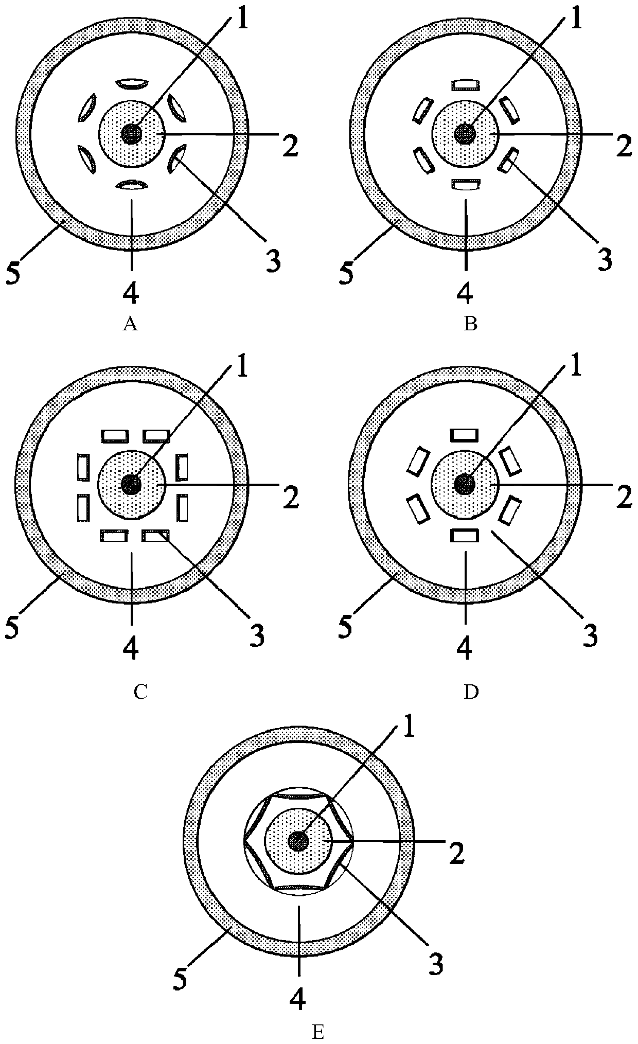
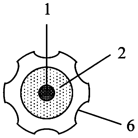
[0045] The erbium-doped optical fiber core rod is prepared by MCVD combined with chelate vapor deposition method. Firstly, the quartz deposition tube is preheated, oxidized and impurity-removed and eroded sequentially; Reaction material SiCl 4 、Er(TMHD) 3 , AlCl 3 、GeCl 4 The flow rate, as shown in Table 2, starts to deposit the core layer in the tube, the deposition temperature is 1895 ° C, and the rotation speed is 30 rpm / min; after the deposition is completed, 5 sccm of Cl 2 The quartz tube is collapsed into a solid rod. Secondly, the Au film is coated on the surface of the mandrel by magnetron sputtering, and then the surrounding groove is machined longitudinally along the surface of the mandrel, such as figure 2 shown; then the mandrel was put into a special tubular resistance furnace, and the carbon nanotube layer was prepared by chemical vapor deposition in situ growth method, with ferrocene as catalyst and xylene as carbon source, and ferrocene was dissolved in xy...

Embodiment 2

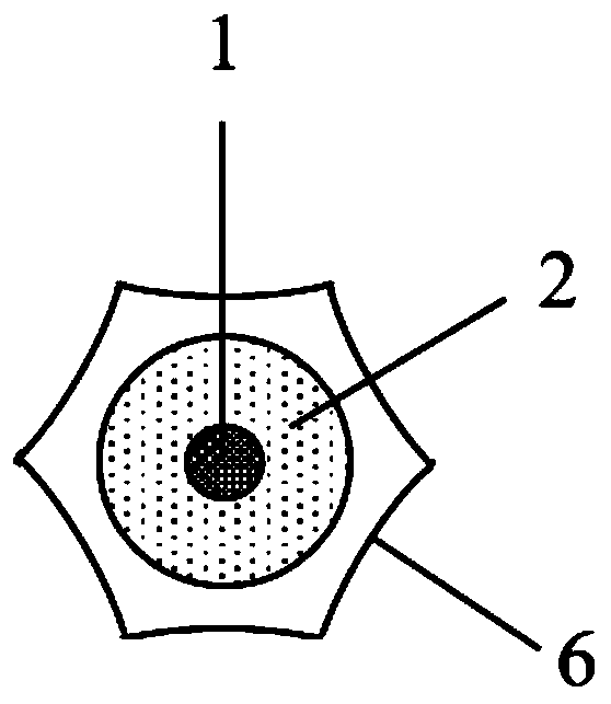
[0047] The preparation method of the erbium-doped optical fiber core rod and the setting of the reaction materials when depositing the fiber core and the transition layer are the same as in the first embodiment, as shown in Table 2. After the surface of the mandrel is coated with Au film, the surrounding groove is machined longitudinally along the surface of the mandrel, such as image 3 Shown; The method for preparing the carbon nanotube layer on the mandrel groove is as embodiment one, and the difference is that the growth time is 60min, and the rotating speed is 40rpm / min; after growing the carbon nanotube layer, remove the Au outside the mandrel groove film, and then carry out hydroxylation treatment on the carbon nanotube layer on the mandrel groove, the method is as in Example 1. Finally, according to the geometric parameters of the optical fiber, the appropriate sleeve process is selected to meet the requirements of the core-to-clad ratio of the optical fiber, and the f...

Embodiment 3

[0051] The preparation method of the erbium-doped optical fiber core rod, the shape of the surrounding groove, the preparation process of the carbon nanotube layer and the hydroxylation treatment process are the same as in Example 1, except that the reaction materials are set as shown in Table 3 when depositing the fiber core and the transition layer. Show. After the optical fiber preform is made, select the appropriate sleeve process according to the geometric parameters of the optical fiber to meet the requirements of the core-to-clad ratio of the optical fiber, and draw it at a temperature of 2050 ° C to obtain an erbium-doped optical fiber with a specification of 3.2 / 125 μm, and then The optical fiber is treated under the condition of a hydrogen atmosphere with a temperature of 70-75° C. and a pressure of 5-10 MPa for 20-40 hours.


PUM


Abstract

The invention belongs to the technical field of optical fibers, and particularly relates to an irradiation-resistant erbium-doped optical fiber for the space and a preparation method of the irradiation-resistant erbium-doped optical fiber. The optical fiber solves the problem that the performance of the optical fiber is reduced under a high-energy irradiation condition, and sequentially comprisesan erbium-doped fiber core, a transition layer and a cladding from inside to outside; at least one group of surrounding units are arranged in the cladding; each group of surrounding units are arrangedin the radial direction of the cladding; each group of surrounding units comprises an even number of through holes which are through in the axial direction of the cladding and distributed in the circumferential direction, and a pattern formed by connecting lines of the centers of the through holes is concentric with the erbium-doped fiber core; and the hole wall of each through hole is covered with a hydroxylated carbon nanotube layer. The preparation method comprises the following steps: manufacturing the core rod, processing the groove surrounding the core rod, growing the carbon nanotube layer in the groove, hydroxylating the carbon nanotube layer, treating the sleeve, and performing drawing. Ce and F are introduced into the fiber core, color center generation of the erbium-doped fiberunder a high-energy irradiation condition is reduced, and the hydroxylated carbon nanotube layer is introduced into the irradiation-resistant erbium-doped fiber cladding, so the radiation shielding effect is achieved, and the irradiation resistance of the erbium-doped fiber is greatly improved.

Description

technical field [0001] The invention belongs to the field of optical fiber technology, and in particular relates to a radiation-resistant erbium-doped optical fiber for space and a preparation method thereof. Background technique [0002] With the development of science and technology, erbium-doped optical fiber, as the core device of optical fiber amplifier and super fluorescent light source, is widely used in the fields of optical fiber communication and optical fiber sensing. Especially with the development of space exploration and optical fiber communication, because the emission wavelength of erbium-doped optical fiber corresponds to the communication window of the atmosphere at 1.55 μm, it can not only be used in the internal communication system of spacecraft or the super fiber optic gyroscope in satellites. Fluorescent light sources, and erbium-doped fiber amplifiers can be used to realize laser communication between satellites or space stations and ground base stati...

Claims


Application Information

Patent Timeline
Patent Type & Authority Applications(China)
IPC IPC(8): G02B6/02H01S3/067
CPCG02B6/02H01S3/06716H01S3/06754
Inventor 折胜飞侯超奇郭海涛常畅高崧张岩李艺昭刘波
Owner XI'AN INST OF OPTICS & FINE MECHANICS - CHINESE ACAD OF SCI
Why Eureka
Try Eureka