Metal surface heat protecting coating structure and preparation method and composite material thereof
A technology for metal surface and thermal protection, applied in the direction of surface reaction electrolytic coating, alkali metal silicate coating, metal material coating technology, etc. Problems such as cracking and peeling, achieve high bonding stability, improve bonding force, and increase stability
- Summary
- Abstract
- Description
- Claims
- Application Information
AI Technical Summary
Problems solved by technology
Method used
Image
Examples
preparation example Construction
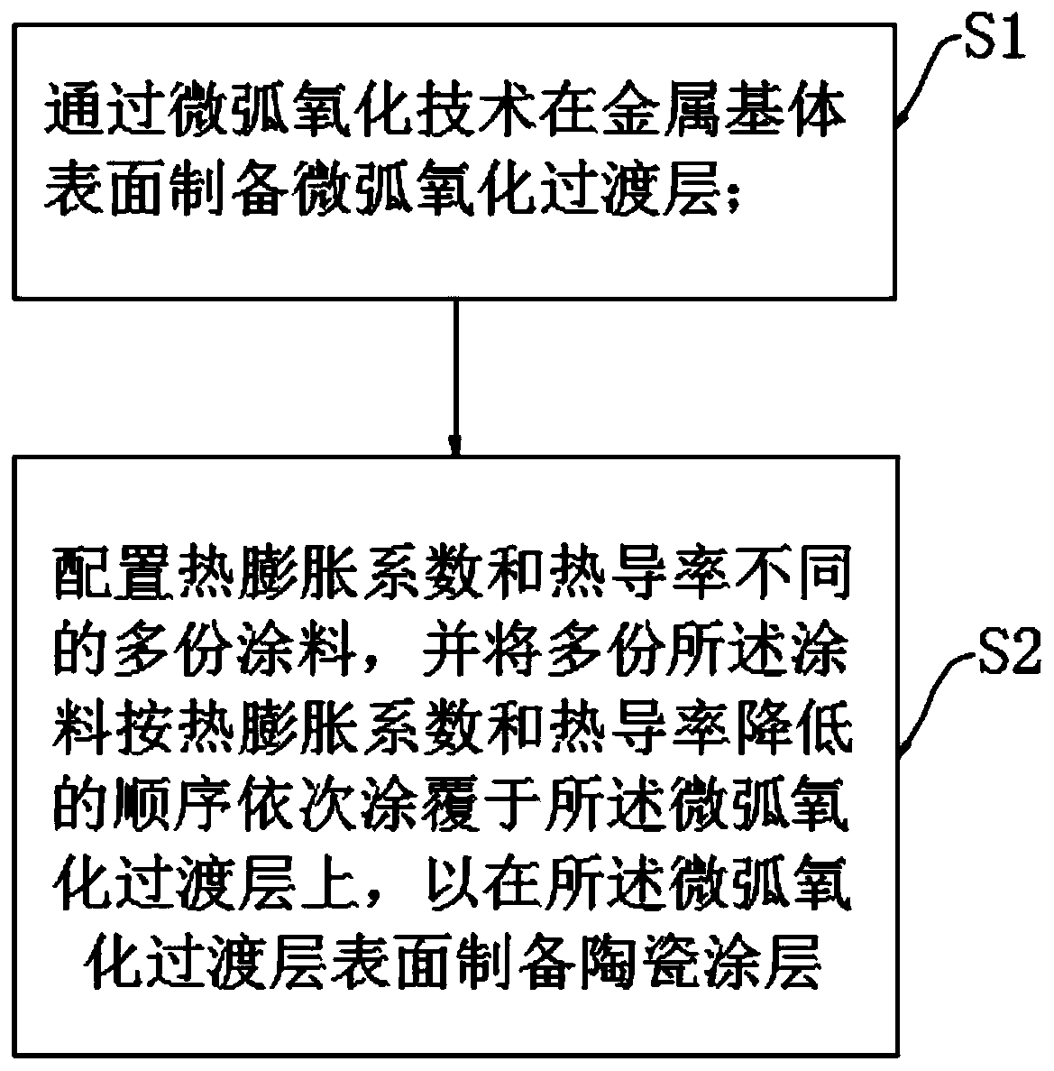
[0039] Embodiments of the present invention also provide a method for preparing a metal surface thermal protection coating structure, such as figure 2 shown, including steps:
[0040] S1, preparing a micro-arc oxidation transition layer 2 on the surface of the metal substrate 1 by micro-arc oxidation technology, as follows:
[0041]The micro-arc oxidation electrolyte is configured so that the micro-arc oxidation transition layer 2 contains at least one of aluminum oxide, magnesium oxide, titanium oxide, magnesium silicate and aluminum silicate, thus, the micro-arc oxidation transition layer 2 is in contact with During the bonding process of the ceramic coating 3, a high-strength chemical bond will be formed to improve the interfacial bonding force. In addition, it is necessary to ensure that the surface of the micro-arc oxidation transition layer 2 is a porous structure with large pores, so as to strengthen its bonding strength with the heat-insulating outer layer. In this ...
Embodiment 1
[0054] In order to solve the problems of poor high temperature resistance of light metals and the mismatch of thermal expansion coefficients between the metal substrate 1 and the coating, this embodiment provides a method for preparing a metal surface thermal protection coating structure. The method includes the following steps:
[0055] 1. Preparation of micro-arc oxidation transition layer on the surface of AZ80 magnesium alloy 2
[0056] 1.1. The electrolyte required for configuration is: mix and stir 20g / L sodium silicate, 10g / L potassium fluoride, 5g / L sodium hydroxide and deionized water, fully dissolve into a solution, and prepare the micro-arc oxidation electrolyte;
[0057] 1.2. Using the AZ80 magnesium alloy metal substrate 1 as the anode and the steel plate as the cathode, under the action of a pulse voltage of 300V, liquid-phase plasma-assisted sintering was carried out for 15 minutes to obtain a micro-arc oxidation transition layer 2 with a thickness of 50 μm.
[...
Embodiment 2
[0065] In order to solve the problems of poor high temperature resistance of light metals and the mismatch of thermal expansion coefficients between the metal substrate 1 and the coating, this embodiment provides a method for preparing a metal surface thermal protection coating structure. The method includes the following steps:
[0066] 1. Preparation of micro-arc oxidation transition layer on the surface of AZ31b magnesium alloy 2
[0067] 1.1. The electrolyte required for configuration is: mix and stir 16g / L sodium silicate, 10g / L potassium fluoride, 8g / L sodium hydroxide and deionized water, fully dissolve into a solution, and obtain a micro-arc oxidation electrolyte;
[0068] 1.2. Using the AZ31b magnesium alloy metal substrate 1 as the anode and the steel plate as the cathode, under the action of 400V pulse voltage, the liquid phase plasma assisted sintering reaction was carried out for 10 minutes to obtain the micro-arc oxidation transition layer 2 with a thickness of 10...
PUM
| Property | Measurement | Unit |
|---|---|---|
| Diameter | aaaaa | aaaaa |
| Length | aaaaa | aaaaa |
| Thickness | aaaaa | aaaaa |
Abstract
Description
Claims
Application Information
 - R&D
- Intellectual Property
- Life Sciences
- Materials
- Tech Scout
- Unparalleled Data Quality
- Higher Quality Content
- 60% Fewer Hallucinations
Browse by: Latest US Patents, China's latest patents, Technical Efficacy Thesaurus, Application Domain, Technology Topic, Popular Technical Reports.
© 2025 PatSnap. All rights reserved.Legal|Privacy policy|Modern Slavery Act Transparency Statement|Sitemap|About US| Contact US: help@patsnap.com


