Laser cladding repairing method for inner hole of rolling mill roller end shaft sleeve and composite device for laser cladding

A technology of laser cladding and repairing method, which is applied in the direction of metal material coating process, coating, etc., can solve the problem of poor processing performance of the repaired part of the fracture toughness repaired part of the bonding force between the clad layer and the substrate, welding clad layer and parts Weak bonding force of the substrate, limited use of the original design structure when changing the scale, etc., to achieve the effect of ensuring performance, reducing temperature gradient and stress-strain unevenness, and strong repairability

Inactive Publication Date: 2021-12-17
泰尔(安徽)工业科技服务有限公司
View PDF0 Cites 2 Cited by
  • Summary
  • Abstract
  • Description
  • Claims
  • Application Information

AI Technical Summary

Problems solved by technology

During the rolling process, the flat surface of the roll end sleeve of the rolling mill will be repeatedly squeezed by the impact load, and at the same time there is axial fretting friction between the work roll and the roll end sleeve of the rolling mill, so the wear of the roll end sleeve of the rolling mill is fast and the service life is short
[0003] For failed rolling mill roll end bushings, the traditional repair methods are resizing, welding repair and laser cladding repair, which have the following problems: 1. The resizing of old parts is limited by the original design structure, size and material of the parts The performance and feasibility are poor; 2. The bonding force between the welding cladding layer and the part matrix is ​​weak, the heat input is large, the stress and strain are large, and the cladding volume is large, resulting in cracking and deformation; 3. The existing laser cladding repair methods: (1) Carbon dioxide lasers or fiber lasers are generally used. The laser beam is a Gaussian wave, and the spot energy distribution is uneven, which is not conducive to the quality consistency of the cladding layer; (2) The structure of the cladding layer is single, and the bonding force between the cladding layer and the substrate is low. The fracture toughness of the part and the processing performance of the repaired part are poor; (3) The heating furnace and heating belt are used for preheating and post-heat treatment, which has the disadvantages of large heat loss and rapid temperature drop, and the temperature of the part will drop after a period of cladding processing When the temperature is below the required preheating temperature range, it is necessary to stop the operation and heat up; the temperature rises slowly and the detection accuracy is poor; (4) using the point heat source input method, there is a difficult balance between the equipment power density capability, processing efficiency, and cladding layer quality Contradictions, the specific analysis is as follows: According to the specific energy Es formula: Es=P / (DV) laser power P, spot diameter D and scanning speed V, when the scanning speed and spot diameter are constant, the cladding layer dilution rate increases with the laser beam power When the depth of the cladding layer reaches the limit, the incident laser energy exceeds the thermal conductivity of the material, and when the thickness of the cladding layer cannot continue to increase with the increase of the incident power, the power density of the cladding area increases with the The incident laser power continues to increase, and the liquid metal in the molten pool begins to vaporize; the laser beam irradiates the metal vapor above the molten pool to form a plasma air mass, and the plasma will shield the laser beam energy during the cladding process, resulting in unstable laser beam input and convection in the molten pool Intense and chaotic, cladding layer deformation, cracking, and inclusions are intensified; the greater the laser power beyond the process, the more metal the spot will melt in the cladding part as a point-like heat source, and the greater the probability of cladding layer defects; however , the laser power is too small, only the surface cladding layer is melted, and the substrate is difficult to melt. At this time, the surface of the cladding layer is partially unfused, and the metallurgical bonding is poor, and the purpose of cladding cannot be achieved; therefore, when the laser spot is purely point-like input, If the power is small, the substrate will be difficult to melt and cladding cannot be achieved, but if the power is high, the probability of cladding layer defects will increase

Method used


Image

  • Laser cladding repairing method for inner hole of rolling mill roller end shaft sleeve and composite device for laser cladding
  • Laser cladding repairing method for inner hole of rolling mill roller end shaft sleeve and composite device for laser cladding
  • Laser cladding repairing method for inner hole of rolling mill roller end shaft sleeve and composite device for laser cladding

Examples


Embodiment 1

[0054] The roller roller end shaft is 42CrMO, and the surface hardness HB269-302 is designed. After use in 1 year, the working surface wear is destroyed, and the performance of similar materials is required, restore the original size and performance indicators.

[0055] 1 Piecelet assembly dismantling: sequentially dismantling the assembly to ensure that the parts are not damaged, and the spare is stored;

[0056] 2 Cleaning of the shaft sleeve: Clean the surface of the bushing, remove oil, rust. Processing removal of the fatigue layer to be repaired to repair the working surface and exclude local defects, remove layer thickness 3-5mm, and perform 100% Pt flaw detection of the working surface;

[0057] 3 ingredient detection: use the mobile spectrometer to chemical composition analysis of the bushing, combined with the matrix material and the technical requirements for repair alloy materials;

[0058] 4 Pre-pre-heat treatment: the roller end shaft to be repaired is placed in the h...

Embodiment 2

[0065] The roller roller end shaft set is 25Cr2Ni4mov, the surface hardness HRC42-45 is designed. After use 1 year, the wear wear is long, requiring the use of similar materials to repair, restore the original size and performance indicators.

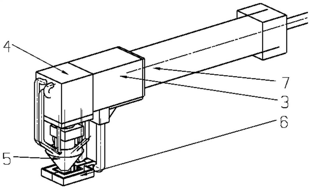
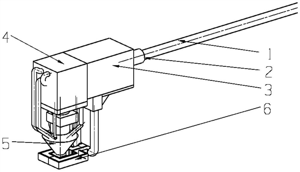
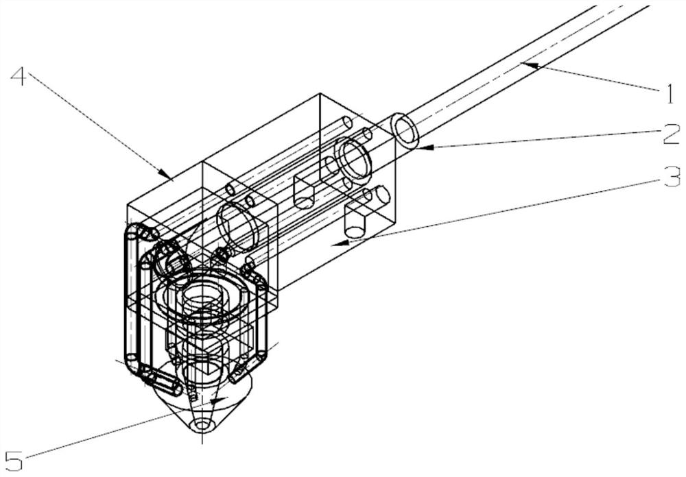
[0066] Among them, step 5 Working surface: The molten alloy material uses a soft powder + transition powder; select a semiconductor laser having a working wavelength of 900-1080 nm as a machining source, and outputs a flat spot spot laser beam; select the core of 1000 μm fiber transmission laser beam; The use of laser molten composite devices for sensing heating and desert; process parameters at the time of cladding: the spot size φ5mm, laser power 2.2kW-2.8KW, induction heating energy consumption percentage 10% -100%, scanning speed 600-720 mm / MIN, the paste is 2.5mm, the layer thickness is 1.2mm to 1.5mm. The rest is the same.

Embodiment 3

[0068] The roller roller end shaft set is 42CrMo, and the surface hardness HRC52-58 is designed. After use in 1 year, the working surface wear is extremely deviation, and the performance of similar materials is required to restore the original size and performance indicators.

[0069] Among them, step 4 Pre-heat treatment: placed the roller end shaft to be repaired in the heat treatment oven for annealing, the temperature rise rate is <100 ° C / h, the annealing temperature 550 ° C-600 ° C, the inclusion length is 4 h, and the curve is slow to room temperature Preheating before the cladding, the preheating temperature of 350 ° C to 400 ° C, using the induction heating device in the laser molten composite device for heating. Among them, step 5 Working surface is cleaved: alloy materials use soft powder + transition powder + strengthening powder; semiconductor laser having a working wavelength of 900-1080 nm as a machining source, output flat top spot laser beam; select the heart di...


PUM

PropertyMeasurementUnit
particle sizeaaaaaaaaaa

Abstract

The invention discloses a laser cladding repairing method for an inner hole of a rolling mill roller end shaft sleeve. The laser cladding repairing method comprises the steps of shaft sleeve assembly disassembly, shaft sleeve surface cleaning, component detection, pre-sequence heat treatment, layered cladding, post-sequence heat treatment, machining, inspection and flaw detection and qualified product delivery. In the step (4) of pre-sequence heat treatment, specifically, preheating is carried out before cladding can be in-furnace heating and heating belt heating; or in-furnace heating and induction device heating are adopted; or the induction device is independently used for heating; and in the step of (6) post-sequence heat treatment, specifically, an induction heating mode can be induction heating or other heating modes. According to the laser cladding repairing method, a cladding layer with high wear resistance, high strength and high binding force is cladded on the surface of the inner hole of a roller end shaft, and the service life of the roller end shaft sleeve is prolonged.

Description

Technical field [0001] The present invention relates to the field of machining, and in particular, a repair method involving the inner bore in the roller end shaft sleeve. Background technique [0002] The rolling roller end shaft is an important connector on the hot rolling production line of the steel. Its main function is to connect the working roller and transmit motor power to it, and achieve the rotation of the upper and lower working rolls to achieve continuous rolling. The rolling roller end shaft in the rolling process will be repeatedly extruded by the impact load, while the working roll and the roller roller end shaft sleeve are axially micro-friction, so that the rolling roller end shaft block is fast and the service life is short. [0003] For the failure rolling roller end shaft, the traditional repair method is a modified utilization, welding repair and laser molten repair, which exists as the following problem: 1. Old part modulatory utilization is limited to part...

Claims


Application Information

Patent Timeline
Patent Type & Authority Applications(China)
IPC IPC(8): C23C24/10B23P6/00
CPCC23C24/103B23P6/00
Inventor 于斌董振启娄家佳王星吴松李申申陈相君徐诚龙陈洛国竹节谭李雯
Owner 泰尔(安徽)工业科技服务有限公司
Why Eureka
Try Eureka