Wear-resistant catalyst coating for ceramic filter tube

A catalyst coating and ceramic technology, applied in the field of denitration catalysts, can solve the problems of low compressive strength, unsatisfactory denitration effect, and high brittleness, so as to improve mechanical properties and wear resistance, improve catalytic destocking effect, and increase growth rate. The effect of toughness

Pending Publication Date: 2022-08-09
安徽紫朔环境工程技术有限公司
View PDF0 Cites 0 Cited by
  • Summary
  • Abstract
  • Description
  • Claims
  • Application Information

AI Technical Summary

Problems solved by technology

However, there are many problems in the above-mentioned catalytic ceramic filter tube during use.
For example, the mechanical properties of the catalyst coating are poor, the compressive strength is low, the brittleness is large, easy to wear, and the wear loss is large, which eventually leads to unsatisfactory detachment effect and unsustainable denitrification effect.

Method used


Image

  • Wear-resistant catalyst coating for ceramic filter tube
  • Wear-resistant catalyst coating for ceramic filter tube
  • Wear-resistant catalyst coating for ceramic filter tube

Examples


Embodiment 1

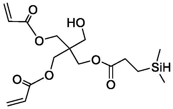
[0033] Preparation of branching agent:

[0034] After mixing 0.1mol pentaerythritol triacrylate and 60mL tetrahydrofuran, heat to reflux, and maintain reflux with condensed water control system, add platinum-carbon catalyst (platinum loading mass fraction is 5%), and slowly dropwise add 40mL containing 0.mol dihydrogen under stirring. The tetrahydrofuran solution of methylchlorosilane, after the dropwise addition was complete, continued to reflux for 4h, stopped the reaction, filtered, and the filtrate was cooled and evaporated under reduced pressure to obtain a branching agent, wherein the added mass of platinum was pentaerythritol triacrylate, dimethyl 0.2% of the total mass of chlorosilanes.

Embodiment 2

[0036] After mixing 0.1mol pentaerythritol triacrylate and 60mL tetrahydrofuran, heat to reflux, and maintain reflux with condensed water control system, add platinum carbon catalyst (platinum loading mass fraction is 5%), and slowly dropwise add 40mL containing 0.98mol dimethyl methacrylate under stirring. After the tetrahydrofuran solution of chlorosilane was added dropwise, the reflux reaction was continued for 7h, the reaction was stopped, filtered, and the filtrate was cooled and evaporated under reduced pressure to obtain a branching agent, wherein the added mass of platinum was pentaerythritol triacrylate, dimethyl chloride 0.6% of the total mass of silane.

Embodiment 3

[0038] Preparation of grafting agent:

[0039] After mixing 0.1 mol of areyl silyl methyl biscarbborane and 60 mL of tetrahydrofuran, under nitrogen protection and ice-water bath, slowly dropwise add 0.2 mol of n-butyllithium hexane solution (the mass fraction of n-butyllithium is 15%) ), after the addition, the temperature was raised to room temperature and the reaction was stirred for 2 hours, and then 30 mL of a tetrahydrofuran solution containing 0.2 mol of dimethylvinylchlorosilane was added dropwise. After the addition was complete, the reaction was stirred at room temperature for 18 hours, and the reaction was stopped. After quenching, the organic layer was extracted several times with ether, washed with deionized water, dried over anhydrous magnesium sulfate, filtered, and rotary evaporated under reduced pressure to obtain the grafting agent.


PUM


Abstract

The invention relates to a wear-resistant catalyst coating for a ceramic filter tube, and belongs to the technical field of denitration catalysts, and the wear-resistant catalyst coating for the ceramic filter tube is prepared by the following steps: step 1, preparing an active component solution; step 2, adding aluminum sol and a dispersing agent into deionized water while stirring, uniformly stirring, then adding the modified basalt fiber, uniformly stirring, then adding the active component solution, performing ultrasonic dispersion, finally adding a pore-enlarging agent, and uniformly stirring to obtain a precursor solution; and step 3, coating the precursor solution on the surface of a ceramic filter tube matrix, and drying and sintering to obtain the wear-resistant catalyst coating. The modified basalt fiber is introduced to improve the mechanical property and wear resistance of the coating, the surface of the modified basalt fiber is coated with a carborane layer and a hydrophilic hyperbranched polymer film layer, and metal oxide is promoted to be uniformly distributed in the catalyst coating.

Description

technical field [0001] The invention belongs to the technical field of denitration catalysts, and in particular relates to a wear-resistant catalyst coating for ceramic filter tubes. Background technique [0002] The energy structure dominated by coal combustion leads to the characteristics of soot-type pollution, and the atmospheric pollutants caused by coal combustion include dust, SO2, NOx, etc. The NOx emission control technologies actually applied to coal-fired boilers in thermal power plants are mainly low NOx combustion technology and dry flue gas denitrification technology (mainly SNCR and SCR technology). Among them, the core of SCR technology is the catalyst, which generally consists of a substrate, a carrier and an active ingredient. Because the ceramic filter tube has the characteristics of high temperature resistance, corrosion resistance and porous, it has good dust retention rate, thermal stability, chemical stability, cleaning resistance, long service life, ...

Claims


Application Information

Patent Timeline
IPC IPC(8): B01J23/34B01J35/06D06M13/513D06M14/00B01D53/86B01D53/56
CPCB01J23/002B01J23/34D06M13/5135D06M14/00B01D53/8628B01J2523/00B01D2258/0283B01J35/58B01J2523/31B01J2523/3712B01J2523/55B01J2523/69B01J2523/72Y02A50/20
Inventor 孙正庭王魁吴昊史宣婷陈拿云
Owner 安徽紫朔环境工程技术有限公司
Why Eureka
Try Eureka