Plasma processes for producing graphene nanosheets

a graphene nanosheet and plasma technology, applied in the field of graphene production, can solve the problems of low carbon feed rate, poor graphitization, and inability to meet the electrical conductivity value, and achieve the effects of low pah content, high quality and safe handling

Active Publication Date: 2020-10-06
RAYMOR IND INC
View PDF9 Cites 1 Cited by
  • Summary
  • Abstract
  • Description
  • Claims
  • Application Information

AI Technical Summary

Benefits of technology

[0061]It has been found that the processes disclosed herein also allow producing high quality graphene nanosheets that have very low PAH content and are safe to handle and to integrate into end-user applications. It also has been found that the processes described herein are effective for increasing the production rate of graphene in a plasma process, thus allowing for economical and large-scale production. For example, it has been found that the production rate can be increased by raising the feed rate of the carbon-containing substance and by simultaneously adapting the design of the nozzle injector. It has also been found that the processes described herein are effective for producing graphene nanosheets with decreased concentrations of polyaromatic hydrocarbons.

Problems solved by technology

While CVD graphene possesses the qualities of true single-layer graphene, it will likely never be produced in quantities necessary for bulk applications.
Exfoliated multi-layer graphene, while being available in bulk quantities suitable for energy storage, filler and conductive ink applications, does not possess the specifications or spectral signature of mono-layer graphene nor can it approach the electrical conductivity values expected for mono-layer graphene.
However, in all cases they operated at low carbon feed rates or obtained poor graphitization.
These publications do not teach operating parameters allowing to scale-up the production while maintaining a high graphene quality.
PAHs can be noxious and carcinogenic as well as pose a serious hazard to humans handling carbon nanoparticles containing PAHs as well as consumers using products that contain PAHs (See Borm P J, et. al., Formation of PAH-DNA adducts after in vivo and vitro exposure of rats and lung cells to different commercial carbon blacks, Toxicology and Applied Pharmacology, 2005 Jun. 1; 205(2): 157-167.).
Moreover, the presence of PAH on carbon surfaces can have detrimental effects on the performance in energy storage applications by blocking small pores and therefore by decreasing the specific surface area.
Such processes, such as Soxhlet extraction, generally require the use of toxic non-polar solvents such as toluene, since the solubility of PAHs is very limited.
However, such processes involving toxic solvents lead to large amounts of waste formed by solvents contaminated with PAHs.
Wet-chemistry PAH removal processes thus have a negative environmental impact and add a large cost to the PAH-free end product.
The use of liquid-phase processes also leads to significant densification of the carbon powder once dried.
Such higher density may be detrimental to further processing such as dispersion, for example.
Indeed, while it is possible to wash away PAHs using wet chemistry processes such as Soxhelet extraction, this adds much cost to the final PAH-free graphene material.

Method used


Image

  • Plasma processes for producing graphene nanosheets
  • Plasma processes for producing graphene nanosheets
  • Plasma processes for producing graphene nanosheets

Examples


example 1

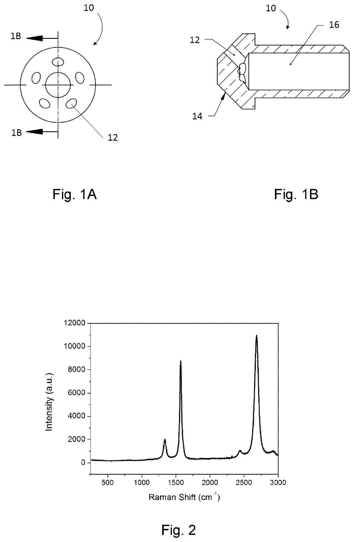
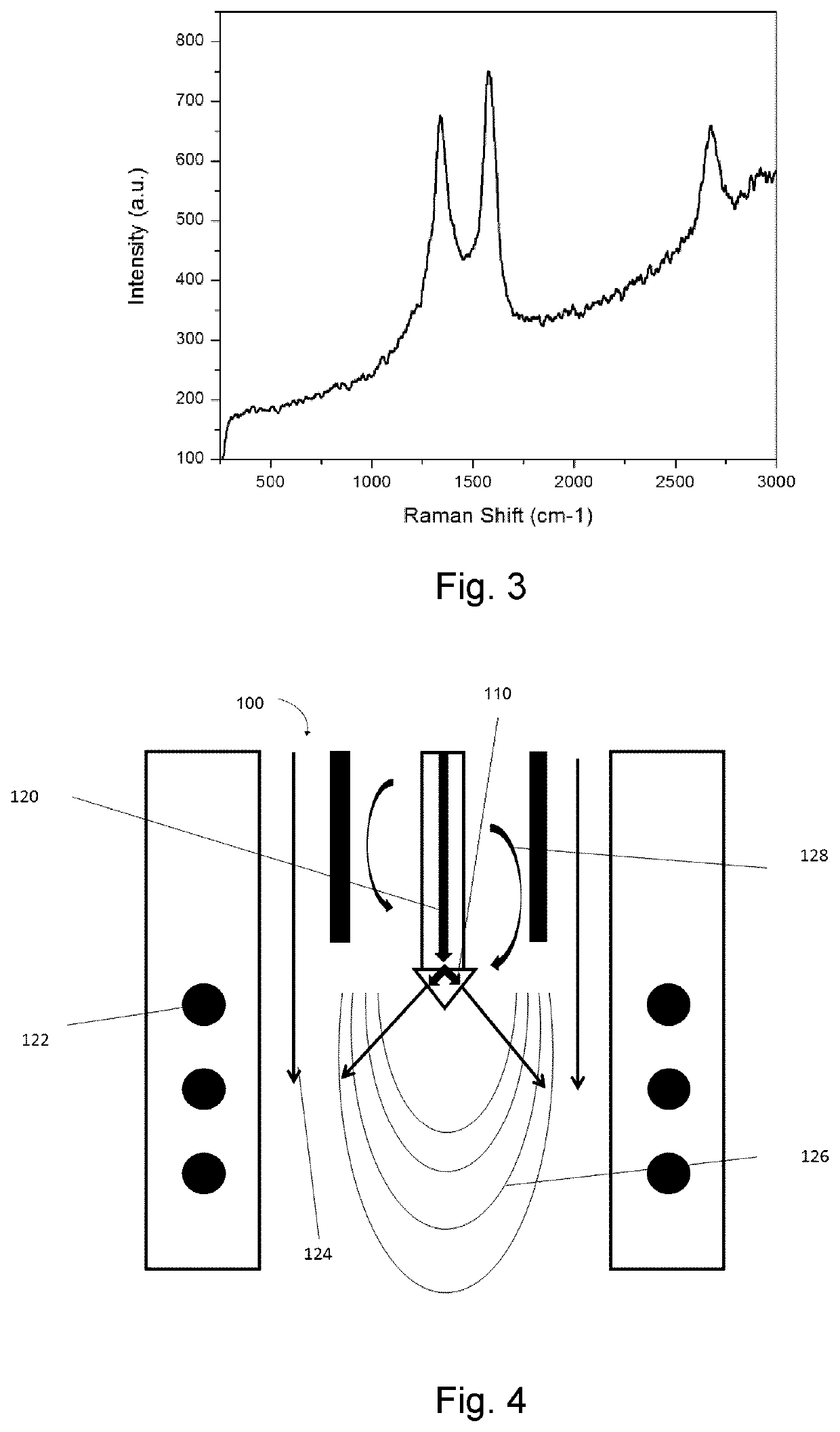
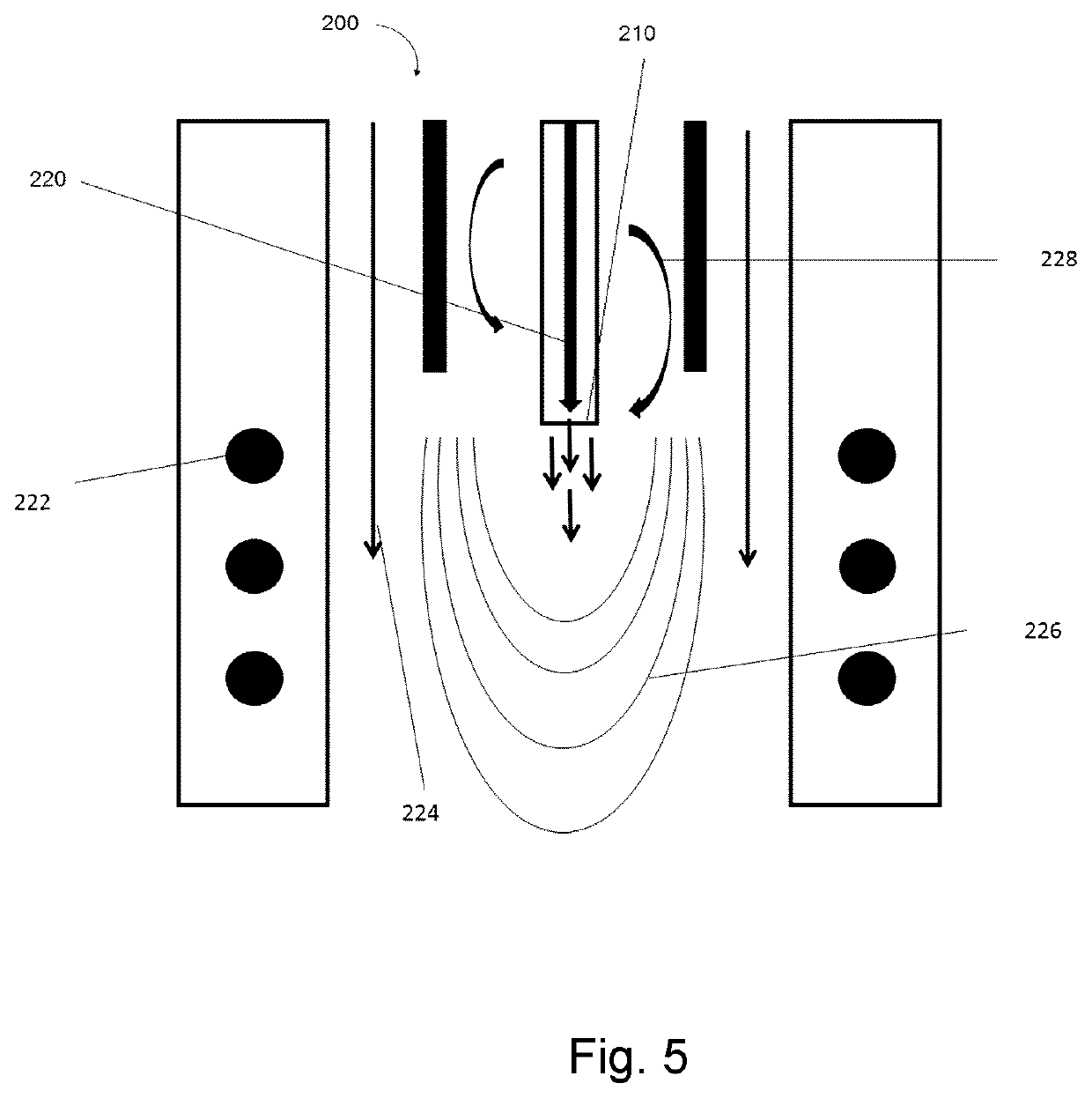
[0200]In one exemplary embodiment, the hydrocarbon precursor material is methane and it is injected into an inductively-coupled plasma torch (ICP) with a maximal plate power of 60 kW. FIG. 4 illustrates the ICP torch 100 as well as the qualitative flow of the gases including the non-carbon containing gases and the carbon containing substance.

[0201]For a power generator delivering 56 kW to an inductively coupled plasma torch (PN-50 model, Tekna, Sherbrooke, Quebec, Canada), and as shown in FIG. 4, 20 slpm argon was used as central swirl gas 128, surrounded by a layer of quench gas (sheath gas) 124 consisting of 174 slpm of argon and 30 slpm of hydrogen gas. 33.6 slpm of natural gas (carbon feed gas) 120 was injected through the injector probe with the designed nozzle 110. Coils 122 conducting the radio frequency alternating current generate the plasma. Qualitative isotherm lines 126 are shown inside the plasma torch. The pressure in the reactor was 500 torr. The injection velocity wa...

example 2

xample

[0209]Conversely, using similar parameters to those described above in Example 1, but injecting the methane with an injection velocity below 60 m / s STP using a single-hole nozzle, a significant fraction of carbon nodules and spheroidal carbon particles were produced leading to the typical Raman spectrum of acetylene black (as shown in FIG. 3). FIG. 5 illustrates the ICP torch 200 used in this counter example as well as the qualitative flow of the gases including the non-carbon containing gases and the carbon containing substance.

[0210]In this example, and as shown in FIG. 5, an injection velocity of 28.6 m / s STP was used. The carbon precursor gas feed rate was 34.7 slpm CH4, and the achieved production rate was 142 g / h. 20 slpm argon is used as central swirl gas 228, surrounded by a layer of quench gas (sheath gas) 224 consisting of 125 slpm of argon and 8 slpm of hydrogen gas. Otherwise the same method and apparatus were used as in Example 1. The carbon precursor gas 220 was ...


PUM

PropertyMeasurementUnit
velocityaaaaaaaaaa
temperatureaaaaaaaaaa

Abstract

Provided are plasma processes for producing graphene nanosheets comprising injecting into a thermal zone of a plasma a carbon-containing substance at a velocity of at least 60 m / s standard temperature and pressure STP to nucleate the graphene nanosheets, and quenching the graphene nanosheets with a quench gas of no more than 1000° C. The injecting of the carbon-containing substance may be carried out using a plurality of jets. The graphene nanosheets may have a Raman G / D ratio greater than or equal to 3 and a 2D / G ratio greater than or equal to 0.8, as measured using an incident laser wavelength of 514 nm. The graphene nanosheets may be produced at a rate of at least 80 g / h. The graphene nanosheets can have a polyaromatic hydrocarbon concentration of less than about 0.7% by weight.

Description

CROSS-REFERENCE TO RELATED APPLICATIONS[0001]The present application is a 35 USC 371 national stage entry of PCT / CA2017 / 051545 filed on Dec. 20, 2017 and which claims priority to U.S. 62 / 437,057 filed on Dec. 21, 2016 and to U.S. 62 / 512,520 filed on May 30, 2017. These documents are hereby incorporated by reference in their entirety.FIELD OF THE DISCLOSURE[0002]The present disclosure relates to the field of graphene production and more particularly to the production of graphene nanosheets using plasma processes, and to the production of graphene nanosheets having a reduced content in polyaromatic hydrocarbons (PAHs).BACKGROUND OF THE DISCLOSURE[0003]Graphene, a material consisting of a few layers or monolayers of sp-2 bonded carbon atoms arranged in a honeycomb lattice, is a material combining high surface area and electrical conductivity with good chemical inertness, as well as outstanding mechanical properties. These qualities render graphene an ideal material for batteries, super...

Claims


Application Information

Patent Timeline
Patent Type & Authority Patents(United States)
IPC IPC(8): C01B32/184B82Y40/00H05H1/30B82Y30/00
CPCH05H1/30C01B32/184B82Y40/00B82Y30/00C01P2004/24C01B2204/30C01B32/186Y02E60/13B01J19/08B01J2219/0894
Inventor KROEGER, JENSLAROUCHE, NICHOLASLAROUCHE, FRÉDÉRIC
Owner RAYMOR IND INC
Why Eureka
Try Eureka