
Single use bioreactor

Active Publication Date: 2020-10-13
LONZA LTD
View PDF41 Cites 1 Cited by
  • Summary
  • Abstract
  • Description
  • Claims
  • Application Information

AI Technical Summary

Benefits of technology

This patent discloses single-use bioreactors and methods for cultivating mammalian cells in large scalable volumes. The bioreactors allow for optimal conditions even in large volumes and maintain a homogeneous environment with respect to pH, dissolved oxygen tension, and temperature. The bioreactors feature enhanced operating characteristics and can produce products with similar quality as products produced in stainless steel bioreactors. The bioreactors are also flexible and can be scaled from laboratory to industry scale. The system includes multiple bioreactors connected to each other, which allows for a well-mixed cell suspension and nutrient feed blending within the bioreactor. Overall, this patent presents a solution for efficient and scalable mammalian cell cultivation.

Problems solved by technology

These SUBs are supplied by vendors as off the shelf designs, limiting the cell culture engineer's ability to match the geometry of the SUB to the geometry of their existing stirred tank reactor (STR) capacity.
This practice, however, further negated the principle of geometric similarity.
The availability of single use bioreactors designed to facilitate universal use in development, in manufacturing operations, and in commercialization of biologics through the cultivation of cells, such as eukaryotic (mammalian) cells, is limited by the state of art.
These limitations stem, in part, from: (i) lack of scalability to large scale operations up to 20,000 L, such as up to 100,000 L; (ii) lack of scalability to a small scale (˜10 mL or even ˜1 mL) development model to permit process development and process characterization in a meaningful manner where the small-scale data produced shows similar and comparable performance to that observed at manufacturing scale; (iii) inadequate mixing and aeration due to the vessel selection and agitator design parameters; and (iv) inadequate design of addition ports to permit application of feeds that are bolus, small volume, concentrated and typically non-physiological in pH and osmolality and / or continuously applied feeds or perfusate / retentate at flow rate ranging from 0.1% v / v per hour to 12.5% v / v per hour.
The current state of the art has additional limitations, such as (i) inadequate design of harvest ports to permit high flow rate without collapsing the harvest tube under the suction head of a pump; (ii) inability to demonstrate process comparability with existing validated bioreactors; (iii) introduction of biologically-active components from the material of contact; and (iv) the sequestering of biologically active medium components or cell-derived metabolites onto the vessel surface, which can result in those components and metabolites becoming limiting or unavailable to the cell present in the bulk aqueous phase.
The current state of art for single use bioreactors is limited to a vessel working volume of from 10 L and up to 2,000 L. The lack of availability of suitable small scale (such as less 10 mL) development models limits the ability of the cell engineer to perform meaningful process development and process characterization experiments to support manufacturing and commercialization of cell culture processes.
Meanwhile, the lack of availability of disposable bioreactors greater than 2,000 L prevents the ability to benefit from the cost of goods reduction that can result from scaling up to beyond 2,000 L.
With regard to bioreactor designs utilizing orbital shaking or rocking, the effectiveness of surface aeration and mixing is limited by a decrease in the surface area as compared to volume as the scale increases; as such, the use of such design can be limited to bioreactors scaled to less than 500 L. For scales of operation of 2000 L and beyond, the hydrodynamic forces needed to create energetic ripples that could penetrate the liquid surface and transfer the mass and energy deep into the liquid bulk would require considerable mechanical strength in the steel holding vessel, disposable bioprocess container, motor and the gearing needed to move the bioprocess container in an orbital motion or tilt it beyond the horizontal plane.
This vortex, however, can create cyclic strains on the impeller shaft, which can lead to material fatigue and failure.
Therefore this mode of mixing is limited to relatively low agitation rates and average energy dissipation rates, which can result in bioreactors that are less well mixed than those stirred bioreactors able to operate at higher agitation rates and P / V.
The low agitation and energy dissipation rates can also limit scale up of such bioreactors.
This uptake requirement can be achieved by employing sintered (microporous spargers) and / or greater sparge rates, which in turn can result in less favorable foaming characteristics due to the vessel operating under a greater interfacial shear environment.
An alternative approach for mitigating this high interfacial shear regime is to increase the oxygen driving force (such as by greatly enriching the blend of oxygen in the sparge gases); however, this approach is also limited due to the concomitant buildup of metabolic CO2, due to poorer mixing in the vessel, and kLa production that can result with off-center agitated bioreactors.
With the single-mounted off-center impeller, relatively high and potentially problematic levels of ‘localized’ impeller-zone shear regimes are required to match the average energy dissipation rate, P / V, produced with a dual or multiple impeller agitated bioreactor.
With regard to centrally mounted impellers in unbaffled vessels, the lack of baffles in stirred bioreactors prevent the deflection of radial flow and under higher agitation rates and P / V's risk the formation of a vortex, which can lead to undesirable surface foaming within the bioreactor.
In addition, without baffles within the bioreactor, the full capability of the impeller's power dissipation ability is not realized.
However, such bioreactors also have flat bottoms, resulting in some areas of concerns when compared with baffled cylindrical bioreactors having a curved base plate or bottom.
Due to the perpendicular flat surfaces of the cube bioreactor, the counter current fluid flow produced by the agitator and deflection from vessel boundary results in greater occurrence of ‘dead zones’ along the edges and corners.
To prevent occurrence of dead zones in the corners, hydrodynamic forces can be increased with scale up or greater power dissipation can be applied; however, both of these alternatives can result in greater mechanical fatigue of the seams at edge / corners.
In addition, the fluid circulation off the bottom of flat bottomed bioreactors is less energetic due to production of counter-current flows from agitator-driven flows and deflection-driven flows from vessel bottom, resulting in less ability to keep cells and / or solids suspended in a flat bottomed bioreactor as compared to bioreactors having base plates designed around the ASME F&D-like geometry.
In current bioreactor designs, surface aeration is inadequate to provide the cellular oxygen uptake rate needed for most fed-batch applications and is highly unlikely to support cell growth in a perfusion mode where cells are retained within the bioreactor.
Additionally, current bioreactors designed to deliver culture aeration through the surface are limited in their ability to be scaled up due to the ever reducing surface area to volume ratio.
This means that, as such designed vessels are scaled up, the efficiency of and capacity for surface aeration deteriorates.
Sintered spargers can produce fine or small gas bubbles that are more easily dispersed within the vessel bulk; in addition, due to their small size, the buoyancy forces of the gas bubbles are small, leading to greater residence time within the liquid bulk and oxygen mass transfer coefficient, kLa, at any given sparge rate.
However, sintered spargers produce greater interfacial cell shear regimes and less effective metabolic CO2 stripping, both of which are critical aspects in ensuring bio-comparability of cell culture processes during scale up and during vessel design transfer.
Furthermore, the scale up of sintered spargers is not well understood and can lead to excessively fast linear velocity or pressure from sparge gases emerging from the sparge hole / pore lead to cellular damage.
With regard to inadequate designs of addition ports that permit application of feeds that are non-physiological in nature, such as feeds that have a very high or low pH or a high osmolality and can result upon exposure to cells in cell damage and death, current disposable bioreactors typically rely on addition ports that discharge onto the culture surface.
While surface discharge may overcome the complex problem of routing the dip tube within the bioreactor and preventing the inadvertent siphoning of bioreactor content out through the dip tube, such bioreactors can suffer from creation of micro-zones of non-physiological environments at and just below the liquid surface.
Secondly, unimpeded flow of cell culture can result in the culture not becoming hypoxic or anoxic whilst passing through such tubings and thereby prevent activation of the released cellular factors which can adversely affect the performance process and quality of the product during further processing.
However, the harvest port and tubing design of all current disposable bioreactors are inadequate in these respects.
The current lack of scalability prevents the development of processes that can be consistently applied to the production of cell culture products.
Indeed, the state of the art is such that cell culture product characteristics are inconsistent across scales, and production processes are for that reason typically modified at different scales to avoid the risk of inconsistent production.
This is time consuming and expensive.

Method used


Image

  • Single use bioreactor
  • Single use bioreactor
  • Single use bioreactor

Examples


example 1

1,000 L Single-Use Bioreactor

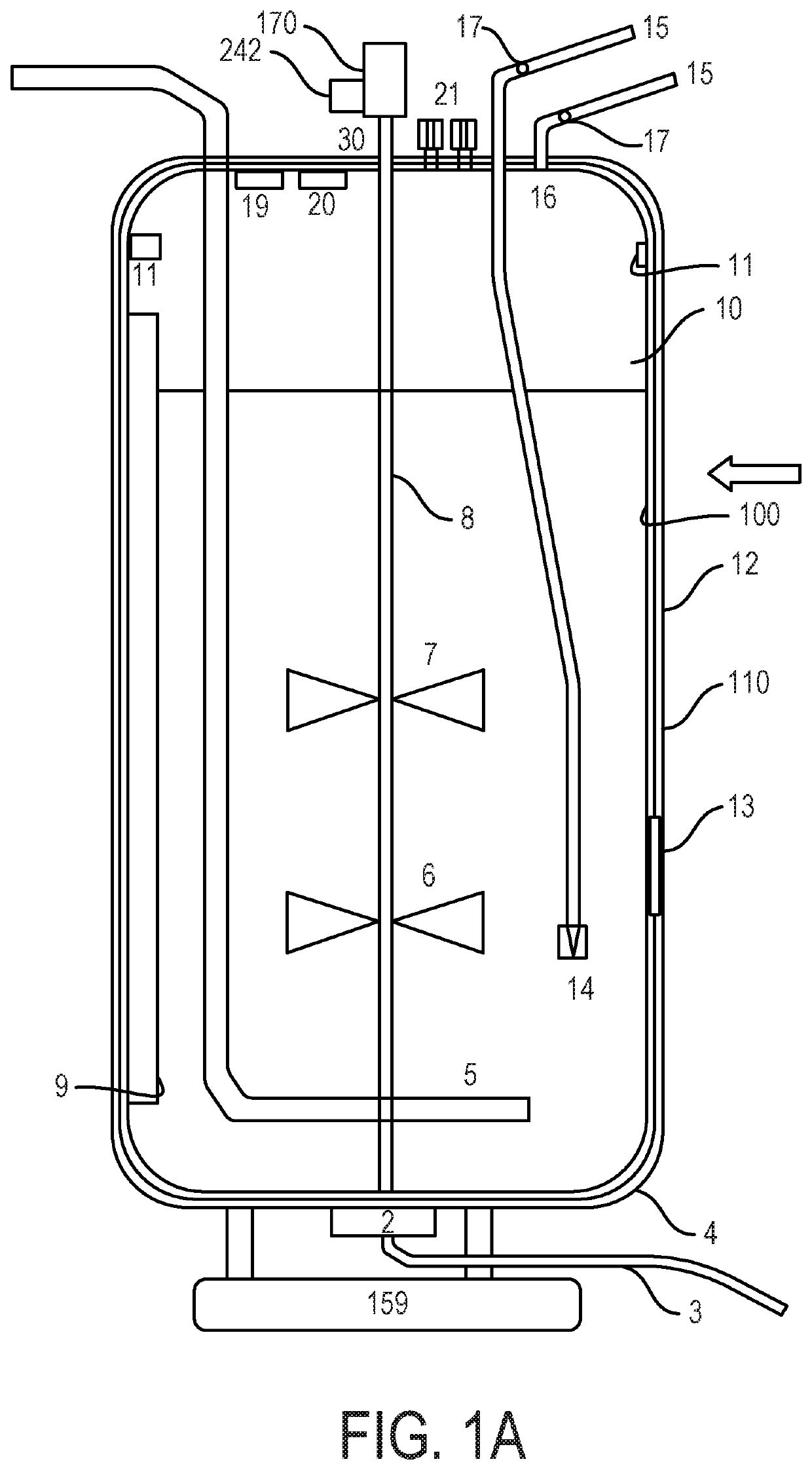
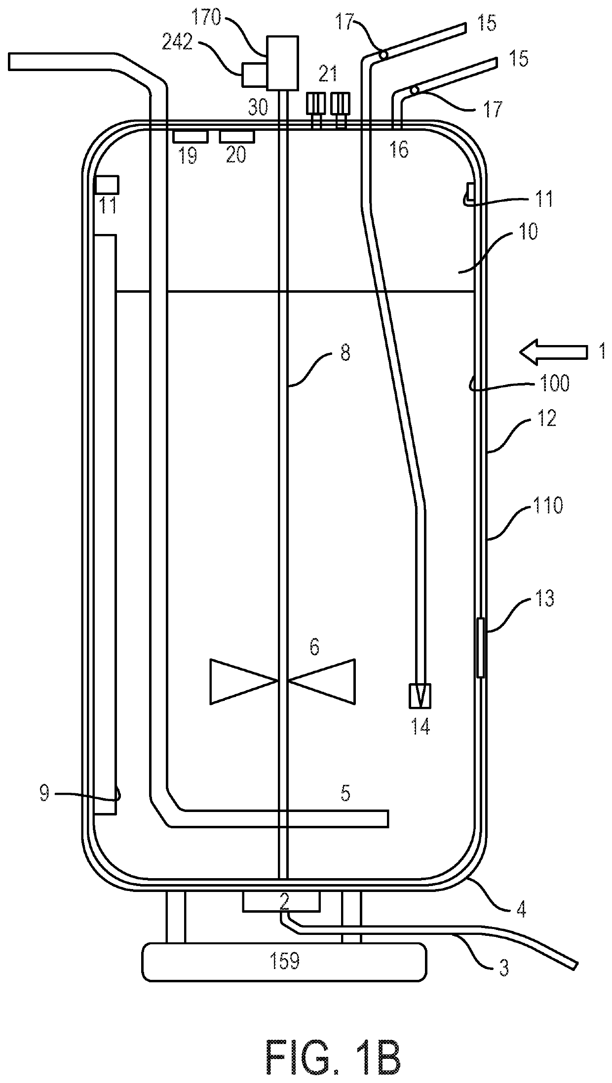
[0346]In this example, a single-use bioreactor of 1,000 L according to the present disclosure is used. A SUB is gamma irradiated (i.e. supplied sterile and ready to use) and is placed into a shell (30). The shell (30) has a jacketed temperature control capable of heating and cooling the culture in combination with an appropriate controller system and thermo circulator. The SUB shell (30) has an integrated motor (motor) for agitating the culture. This is compatible with the controller systems of FIG. 36. The single-use bioreactor has an agitator, a sparger, a gas filter inlet ports for sparger, and an exhaust gas outlet filter port with bifurcating line. It also has seven feed addition ports. Ideally, two are subsurface discharging in the impeller region and one discharging above the impeller region. It also has two medium fill ports, one harvest port designed to enable harvest the complete contents of the single-use bioreactor, one sample port, one conde...

example 2

Reactor Geometry

[0348]This example relates to the effect of changing reactor geometry on scale up of mammalian cell culture processes using multivariate data analysis to compare different geometries and different fill volumes. This approach uncovered a surprising result when working at half volume, which may not have been spotted using conventional data analysis methods.

[0349]Mass transfer studies were performed with two manufacturing scale SUB systems and a miniature SUB system using the gassing-out approach. A scale independent kLaO2 model developed according to the geometry described in U.S. Publication No. US 2011 / 0312087 (referred to herein as “Lonza Geometry”) was used to predict kLaO2 in both SUBs. The results have been compared to results generated using the STR geometry described in U.S. Publication No. US 2011 / 0312087 from 10 to 20,000 L. The vessel geometry has a substantial impact on mass transfer.

[0350]Multivariate analysis of the data showed that there were substantial...

example 3

A 1,000 L Bioreactor Set Up

[0362]The single-use bioreactors of the present disclosure are suitable for use in the production processes described in WO 2017 / 072201 A2, which is incorporated by reference in its entirety herein.

[0363]The bioprocess container shell was a jacketed stainless steel container, which supported the SUB container. The shell incorporated two doors that open outwards for operators to fit the SUB bioprocess container. These were fastened shut by clamps. The shell incorporated a water jacket at the bottom for regulation of temperature. This was connected to the controller of the present disclosure.

[0364]At the bottom of the shell there was a drain port for harvesting and two openings for control probes and sampling. For non-disposable probes the shell had shelving set at 15 degrees from horizontal to support the probes.

[0365]At the top of the bioprocess container holder there was a motor to which the SUB container impeller was connected via a magnetic coupling. Th...


PUM

PropertyMeasurementUnit
volumeaaaaaaaaaa
volumeaaaaaaaaaa
volumeaaaaaaaaaa

Abstract

A single-use bioreactor is provided. The single-use bioreactor may include a bioprocess container, a shell, at least one agitator, at least one sparger, at least one gas filter inlet port for the sparger(s) and headspace overlay, at least one fill port, at least one harvest port, at least one sample port, and at least one probe. In examples, at least one controller may monitor and control one or more parameters associated with the single-use bioreactor A method to cultivate and propagate mammalian cells is also provided. The method may include cultivating under suitable conditions and in a suitable culture medium in a first single-use bioreactor, transferring the medium containing the cells obtained by propagation from the at least one mammalian cell is into a second single-use bioreactor, transferring the medium containing the cells obtained by propagation from the at least one mammalian cell is into a third single-use bioreactor, and cultivating the cells in the third bioreactor.

Description

CROSS REFERENCE TO RELATED APPLICATIONS[0001]This application claims priority to and the benefit of U.S. Provisional Application No. 62 / 345,381, filed on Jun. 3, 2016, the contents of which are incorporated herein by reference. U.S. Provisional Application No. 62 / 354,216, filed Jun. 24, 2016, and the following publications U.S. Patent Publication No. 2011 / 0312087, U.S. Patent Publication No. 2017 / 0107476, WO Publication No. WO 2017 / 072201, are each hereby incorporated by reference in their entirety.BACKGROUND ART[0002]Bioreactors, or apparatuses in which biological reactions or processes can be carried out on a laboratory or industrial scale, are used widely within the biopharmaceutical industry. Bioreactors can be used in fed-batch applications, wherein substrates are supplied at certain times to a bioreactor and wherein products remain in the bioreactor until the end of the reaction time, or in perfusion applications, wherein a continuous supply of substrate is supplied to the bio...

Claims


Application Information

Patent Timeline
Patent Type & Authority Patents(United States)
IPC IPC(8): C12M1/00B01F7/00C12M1/06B01F3/04B01F7/16B01F15/00
CPCB01F7/00633C12M23/26C12M23/28C12M29/00C12M27/20B01F3/04106C12M29/06B01F7/00375B01F7/00033C12M27/02B01F15/0085B01F7/1675C12M23/14B01F2215/0431B01F2215/0459B01F23/231B01F27/053B01F27/1134B01F27/191B01F27/86B01F35/513
Inventor JAQUES, COLIN MARKKHAN, MOHSAN WASEEMDE BARROS COSTA, RITA D'ORNELAS P.BEANEY, ANTHONYVALENTINE, DAVID
Owner LONZA LTD
Learn More