Spectral bio-imaging of the eye

a bio-imaging and eye technology, applied in the field of spectral bio-imaging of the eye, can solve the problems of large size and configuration of remote sensing spectral imaging systems, limited use of air and satellite-born applications, and inability to choose,

Inactive Publication Date: 2001-10-25
APPLIED SPECTRAL IMAGING
View PDF0 Cites 55 Cited by
  • Summary
  • Abstract
  • Description
  • Claims
  • Application Information

AI Technical Summary

Benefits of technology

[0019] Apparatuses in accordance with the above features differ from the conventional slit- and filter type imaging spectrometers by utilizing an interferometer as described above, therefore not limiting the collected energy with an aperture or slit or limiting the incoming wavelength with narrow band interference or tunable filters, thereby substantially increasing the total throughput of the system.
[0059] The present invention successfully addresses the shortcomings of the presently known configurations by providing an image of the eye which enhances spectral signatures of constituents thereof, characterized by high spatial and spectral resolutions.

Problems solved by technology

However, the high cost, size and configuration of remote sensing spectral imaging systems (e.g., Landsat, AVIRIS) has limited their use to air and satellite-born applications [See, Maymon and Neeck (1988) Proceedings of SPIE - Recent Advances in Sensors, Radiometry and Data Processing for Remote Sensing, 924, pp.
The inability to visualize the two-dimensional image before the whole measurement is completed makes it impossible to choose, prior to making a measurement, a desired region of interest from within the field of view and / or to optimize the system focus, exposure time, etc.
It should be further noted that slit-type imaging spectrometers have a major disadvantage since most of the pixels of one frame are not measured at any given time, even though the fore- optics of the instrument actually collects incident light from all of them simultaneously.
Furthermore, slit-type spectral imagers require line scanning to collect the necessary information for the whole scene, which may introduce inaccuracies to the results thus obtained.
However, AOTFs and LCTFs have the disadvantages of (i) limited spectral range (typically, .lambda..sub.max=2.lambda..sub.min) while all other radiation that falls outside of this spectral range must be blocked, (ii) temperature sensitivity, (iii) poor transmission, (iv) polarization sensitivity, and (v) in the case of AOTFs an effect of shifting the image during wavelength scanning.
All these types of filter and tunable filter based systems have not been used successfully and extensively over the years in spectral imaging for any application, because of their limitations in spectral resolution, low sensitivity, and lack of easy-to-use and sophisticated software algorithms for interpretation and display of the data.
However the suggested screening schedule is expensive, and for some individuals even the current expensive screening is not sufficient because patients occasionally develop severe retinopathy between scheduled examinations.
Fluorescein angiography of the retina is routinely performed today, but it is invasive, unpleasant, and causes occasional deaths.
Furthermore, the additional information obtained by fluorescein angiography does not help categorize patients into those who may benefit from immediate laser treatment and those who will not [Ferris (1993) (commentary) JAMA 269:1290-1].
Because of the high oxygen needs of the retina, any alteration in circulation such as seen in diabetic retinopathy, hypertension, sickle cell disease, and vascular occlusive diseases results in functional impairment and extensive retinal tissue.

Method used


Image

  • Spectral bio-imaging of the eye
  • Spectral bio-imaging of the eye
  • Spectral bio-imaging of the eye

Examples


example 1

The Measurement Apparatus

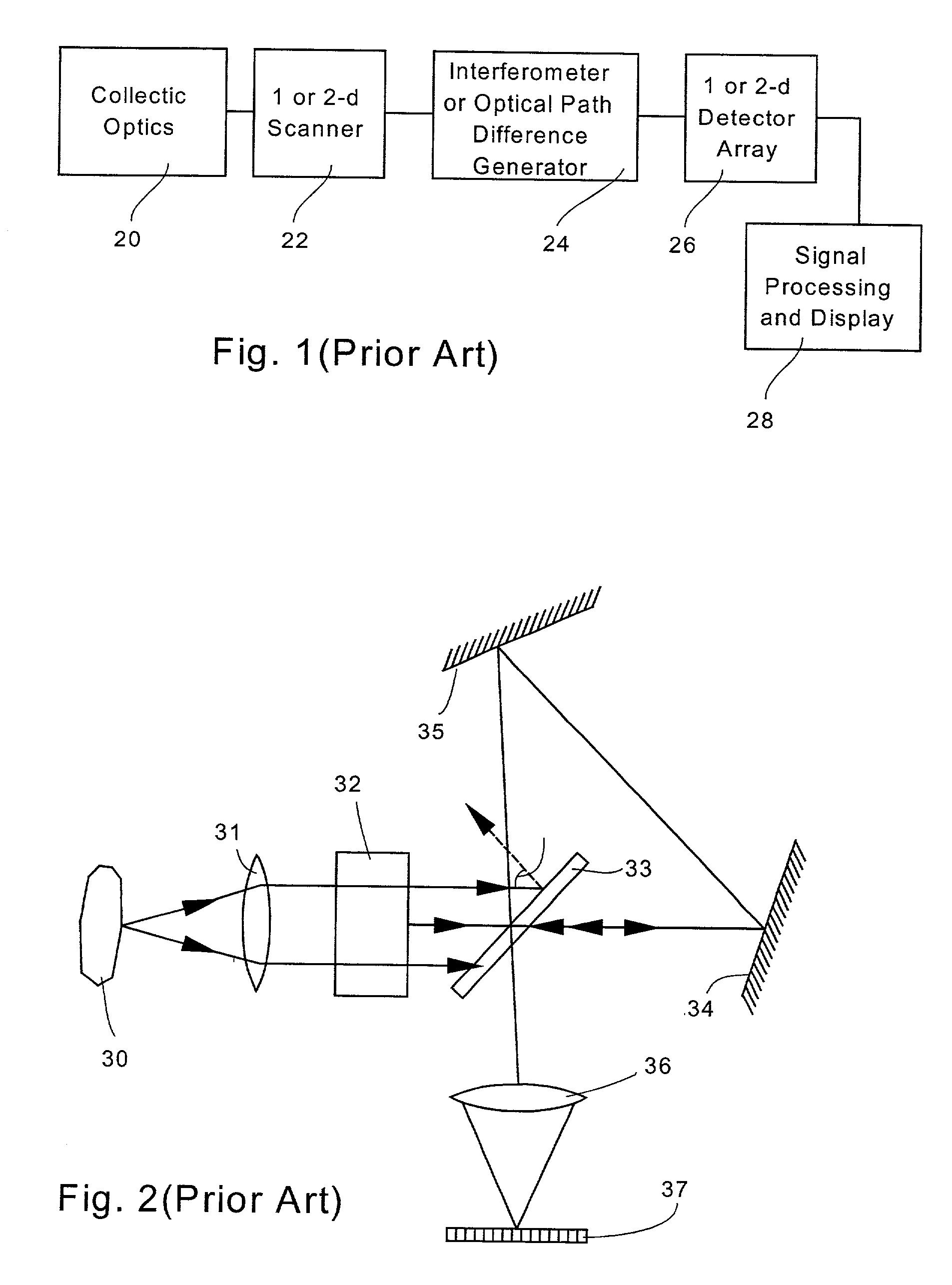
[0106] FIG. 1 is a block diagram illustrating the main components of a prior art imaging spectrometer disclosed in U.S. Pat. No. 5,539,517. This imaging spectrometer is constructed highly suitable to implement the method of the present invention as it has high spectral (Ca. 4-14 nm depending on wavelength) and spatial (Ca. 30 / M .mu.m where M is the effective microscope or fore optics magnification) resolutions.

[0107] Thus, the prior art imaging spectrometer of FIG. 1 includes: a collection optical system, generally designated 20; a one-dimensional scanner, as indicated by block 22; an optical path difference (OPD) generator or interferometer, as indicated by block 24; a one-dimensional or two-dimensional detector array, as indicated by block 26; and a signal processor and display, as indicated by block 28.

[0108] A critical element in system 20 is the OPD generator or interferometer 24, which outputs modulated light corresponding to a predetermined set of lin...

example 2

Display and Analysis of Spectral Images

[0125] a. General

[0126] As mentioned above, a spectral image is a three dimensional array of data, I(x,y,.lambda.), that combines spectral information with spatial organization of the image.

[0127] As such, a spectral image is a set of data called a spectral cube, due to its dimensionality, which enables the extraction of features and the evaluation of quantities that are difficult, and in some cases even impossible, to obtain otherwise.

[0128] Since both spectroscopy and digital image analysis are well known fields that are covered by an enormous amount of literature [see, for example, Jain (1989) Fundamentals of Digital Image Processing, Prentice-Hall International], the following discussion will focus primarily on the benefit of combining spectroscopic and imaging information in a single data set i.e., a spectral cube.

[0129] One possible type of analysis of a spectral cube is to use spectral and spatial data separately, i.e., to apply spectral...

example 4

Spectral Imaging of Moving Objects

[0168] According to the present invention provided are spectral images of the eye collected preferably by an interferometer based spectral imager.

[0169] Since, in order to perform a measurement, an interferometer based spectral imager must collect several frames of an examined object in a period of time that varies from ca. 5 to 60 seconds, a considerably longer period of time as compared with a camera or video camera snapshot, spectral imaging of moving objects, like the eye results in blurring of the image of the object and in disrupting the algorithm used to calculate the spectrum of each pixel thereof.

[0170] Indeed, while using the apparatus disclosed in U.S. Pat. No. 5,539,517 one This is indeed the case in many applications, such as when spectral imaging is used for color karyotyping and color banding of chromosomes as disclosed in Schroeck et al. (1996) Multicolor spectral karyotyping of human chromosomes. Science 273:494-497. However, in oth...


PUM

PropertyMeasurementUnit
ODaaaaaaaaaa
timeaaaaaaaaaa
wavelengthsaaaaaaaaaa

Abstract

A spectral bio-imaging method for enhancing pathologic, physiologic, metabolic and health related spectral signatures of an eye tissue, the method comprising the steps of (a) providing an optical device for eye inspection being optically connected to a spectral imager; (b) illuminating the eye tissue with light via the iris, viewing the eye tissue through the optical device and spectral imager and obtaining a spectrum of light for each pixel of the eye tissue; and (c) attributing each of the pixels a color according to its spectral signature, thereby providing an image enhancing the spectral signatures of the eye tissue.

Description

[0001] This is a divisional of U.S. patent application Ser. No. 08 / 942,122, filed Oct. 1, 1997, which is a continuation-in-part of U.S. patent application Ser. No. 08 / 571,047, filed Dec. 12, 1995, which is a continuation-in-part of U.S. patent application Ser. No. 08 / 392,019, filed Feb. 21, 1995, now U.S. Pat. No. 5,539,517, issued Jul. 23, 1996, which is a continuation-in-part of U.S. patent application Ser. No. 08 / 107,673, filed August 18, 1993, now abandoned.FIELD AND BACKGROUND OF THE INVENTION[0002] The present invention relates to spectral imaging in general and, more particularly, to spectral bio-imaging of the eye which can be used for non-invasive early detection and diagnosis of eye diseases and for detection of spatial organization, distribution and quantification of cellular and tissue natural constituents, structures and organelles, tissue vitality, tissue metabolism, tissue viability, etc., using light reflection, scattering and emission, with high spatial and spectral...

Claims


Application Information

Patent Timeline
Patent Type & Authority Applications(United States)
IPC IPC(8): A61B3/12A61B3/11A61B5/00C12Q1/68G01J3/02G01J3/12G01J3/26G01J3/28G01J3/44G01J3/453G01N21/64G01N33/50G01N33/569G01N33/58G06V10/88
CPCA61B5/14555A61B5/411A61B5/7257C12Q1/6816C12Q1/6841C12Q1/6883G01J3/02G01J3/12G01J3/1256G01J3/26G01J3/2823G01J3/4406G01J3/453G01J3/4535G01J2003/2866G01N21/6428G01N21/6456G01N21/6458G01N33/5005G01N33/56966G01N33/582G01N2021/6417G01N2021/6423G01N2021/6441G06K9/00127G06K9/76A61B3/10G06V20/69G06V10/88
Inventor CABIB, DARIOADEL, MICHAELBUCKWALD, ROBERT A.
Owner APPLIED SPECTRAL IMAGING
Why Eureka
Try Eureka