Process for producing a photoelectric conversion device

a technology process, which is applied in the direction of crystal growth process, sustainable manufacturing/processing, final product manufacture, etc., can solve the problems photoelectric conversion device, and lower conversion efficiency of photoelectric conversion devi

Inactive Publication Date: 2002-08-01
SEMICON ENERGY LAB CO LTD
View PDF0 Cites 44 Cited by
  • Summary
  • Abstract
  • Description
  • Claims
  • Application Information

AI Technical Summary

Problems solved by technology

The production amount thereof is limited by the supply capacity of the semiconductor substrate.
However, this photoelectric conversion device has lower conversion efficiency than the photoelectric conversion device using monocrystal silicon or polycrystal silicon.
Furthermore, this photoelectric conversion device has problems such as deterioration by light.
Thus, the use of this photoelectric conversion device is limited to products having a small power consumption, such as a pocket calculator.
Thus, the material which can be used for the substrate is limited.
Particularly in the melting recrystallization method, the material for the substrate is limited to a material enduring the melting point of silicon, that is, 1412.degree. C.
However, such a substrate is not necessarily suitable for a reduction in production costs.
Thus, if a conventional crystallizing technique is used, this substrate is distorted to generate large deformation.
Since the substrate is made of a material essentially different from silicon, a monocrystal film cannot be obtained even if heat treatment for crystallization is merely performed.
The grain size of the polycrystal film is not easily made large.
Originally, however, all of the catalyst materials used to promote the crystallization are materials unpreferable for crystalline silicon.
However, even if the concentration is relatively low, the element suitable for the catalyst material, when taken in silicon, generates a defect level because the element is a metal.
Thus, it is evident that this defect level causes the deterioration of important characteristics for a photoelectric conversion device, such as the lifetime of carriers.
In the case that silicon has many defect levels, the carriers are trapped into the defect levels on their way to become extinct.
That is, the photoelectric conversion characteristic of the photoelectric conversion device deteriorates.

Method used


Image

  • Process for producing a photoelectric conversion device
  • Process for producing a photoelectric conversion device
  • Process for producing a photoelectric conversion device

Examples


embodiment 1

[0029] Embodiment 1

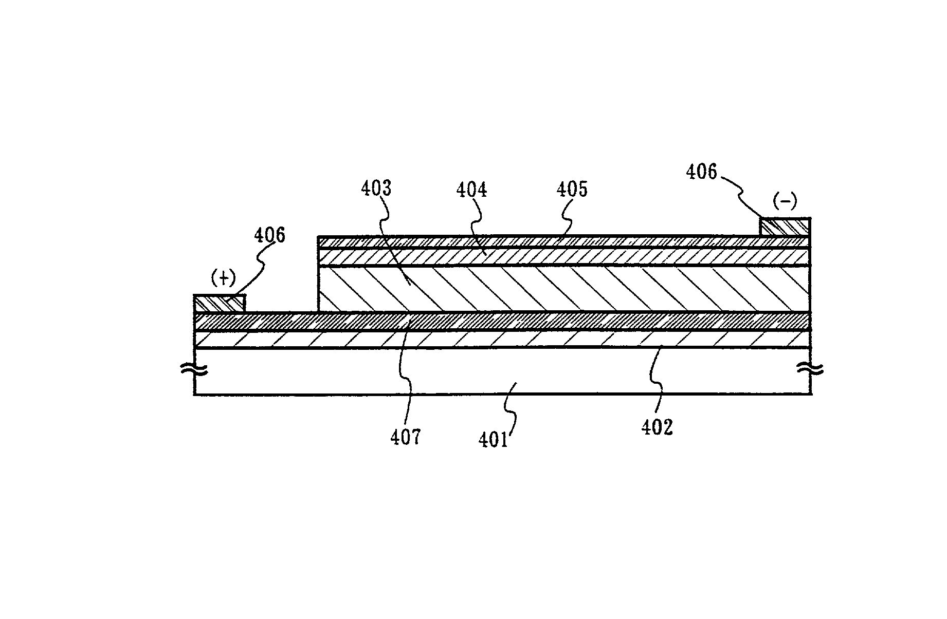
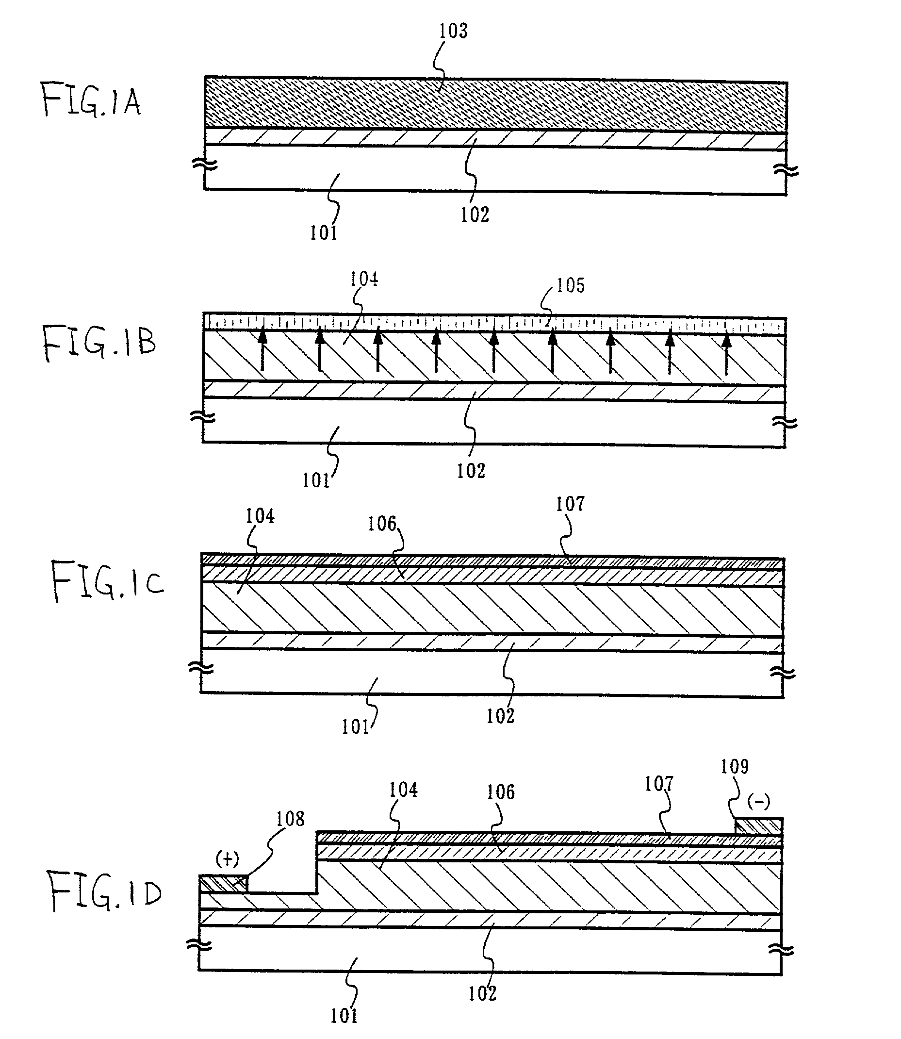
[0030] Referring to FIG. 1, the following will describe a process for producing a photoelectric conversion device by forming a catalyst element for promoting the crystallization of silicon adhesively to an amorphous silicon film, crystallizing the amorphous silicon film by heat treatment, and removing the catalyst element remaining after the crystallization outside the crystalline silicon film.

[0031] Referring to FIG. 1, a silicon oxide film 102 is formed as an undercoat on a glass substrate (for example, a 1737 glass substrate made by Corning Incorporated) 101 to have a thickness of 0.3 .mu.m. This silicon oxide film 102 may be formed by plasma CVD using tetramethyl silicate (TEOS) as raw material, or by sputtering. Next, an amorphous silicon film 103 is formed by plasma CVD using silane gas as raw material.

[0032] The formation of the amorphous silicon film 103 may be performed using reduced-pressure thermal CVD, sputtering or vacuum evaporation as well as plasma...

embodiment 2

[0044] Embodiment 2

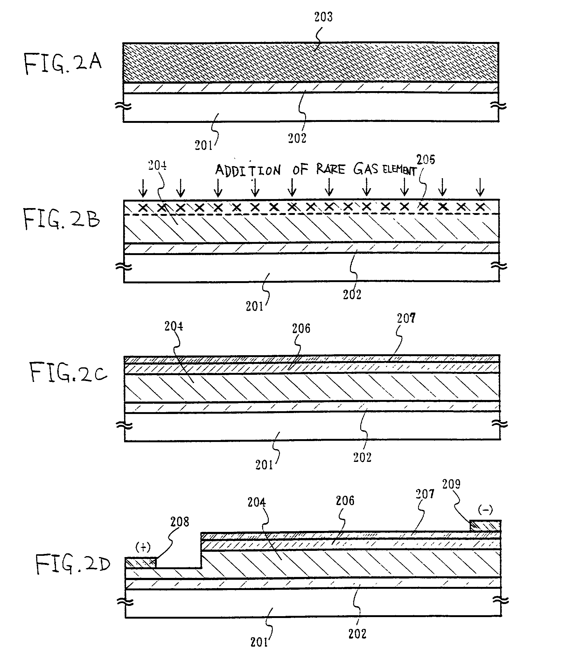
[0045] According to the process for producing a photoelectric conversion device of the present embodiment, in the step of removing the catalyst element for promoting the crystallization of silicon after crystallization, a method of using ion implantation or ion doping is adopted to add a rare gas element into the surface of the crystalline silicon film.

[0046] Referring to FIG. 2, a silicon oxide film 202 is formed as an undercoat on a glass substrate 201 to have a thickness of 0.3 .mu.m. This silicon oxide film is formed by plasma CVD using tetramethyl silicate (TEOS) as raw material. This film may be formed by sputtering. Next, silane gas is used as raw material to form an amorphous silicon film 203 by plasma CVD. Next, the workpiece is immersed into ammonium hydrogen peroxide, and kept at 70.degree. C. for 5 minutes, thereby forming an oxide film (not illustrated) on the surface of the amorphous silicon film 203. A solution of acetate nickel is applied onto the ...

embodiment 3

[0056] Embodiment 3

[0057] The following will describe an embodiment wherein an amorphous silicon film formed as a gettering site on a crystalline silicon film formed using a catalyst element is selectively removed.

[0058] Referring to FIG. 5A, a silicon oxide film 502 is formed as an undercoat on a glass substrate 501 in the same way as in the embodiment 1, so as to have a thickness of 0.3 .mu.m. Next, an amorphous silicon film is made from silane gas as raw material by plasma CVD, and then a catalyst element is introduced thereto so as to crystallize the amorphous silicon film. In this way, a crystalline silicon film 503 is formed. The steps described above are performed in the same way as in the embodiment 1.

[0059] Next, a barrier layer 504 is formed on the surface of the crystalline silicon film 503. To form the barrier layer, a chemical oxide produced by treatment with ozone water may be used. The chemical oxide may also be produced by treatment with an aqueous solution wherein h...


PUM

PropertyMeasurementUnit
melting pointaaaaaaaaaa
temperatureaaaaaaaaaa

Abstract

A catalyst element remaining in a first semiconductor film subjected to a first heat treatment (crystallization) is moved and concentrated/collected by subjecting a second semiconductor film which is formed on the first semiconductor film and contains a rare gas element to a second heat treatment. That is, the rare gas element is incorporated into the second semiconductor film to generate a strain field as a gettering site.

Description

[0001] 1. Field of the Invention[0002] The present invention relates to a photoelectric conversion device wherein a photoelectric conversion layer composed of a crystalline silicon film is formed on a substrate, and a process for producing the same.[0003] 2. Related Art[0004] A photoelectric conversion device can be produced using any one of various semiconductor materials and organic compound materials. However, the photoelectric conversion device is industrially produced using silicon mainly. The photoelectric conversion device using silicon can be classified into a bulk type photoelectric conversion device using a wafer made of monocrystal silicon or polycrystal silicon and a thin film type photoelectric conversion device wherein a silicon film is formed on a substrate. For the bulk type photoelectric conversion device, a semiconductor substrate (such as a silicon wafer) is necessary in the same way as for a LSI (large-scale integrated circuit). The production amount thereof is l...

Claims


Application Information

Patent Timeline
Patent Type & Authority Applications(United States)
IPC IPC(8): H01L27/14C30B1/02H01L21/20H01L31/04H01L31/18H01L31/20
CPCC30B1/023H01L21/2022H01L21/26506H01L21/3226H01L31/028H01L31/072H01L31/1804H01L31/1872H01L31/208C30B29/06Y02E10/547Y02P70/50H01L21/02425H01L21/02422H01L21/02488H01L21/0245H01L21/02672
Inventor YAMAZAKI, SHUNPEIARAI, YASUYUKI
Owner SEMICON ENERGY LAB CO LTD
Why Eureka
Try Eureka