

Hydrolysis stable self-etching,self-priming adhesive
a self-priming adhesive and self-etching technology, applied in the field of hydrolysis, can solve the problems of inherently disadvantageous two-way procedures
- Summary
- Abstract
- Description
- Claims
- Application Information
AI Technical Summary
Benefits of technology
Problems solved by technology
Method used
Image

Examples
example 1
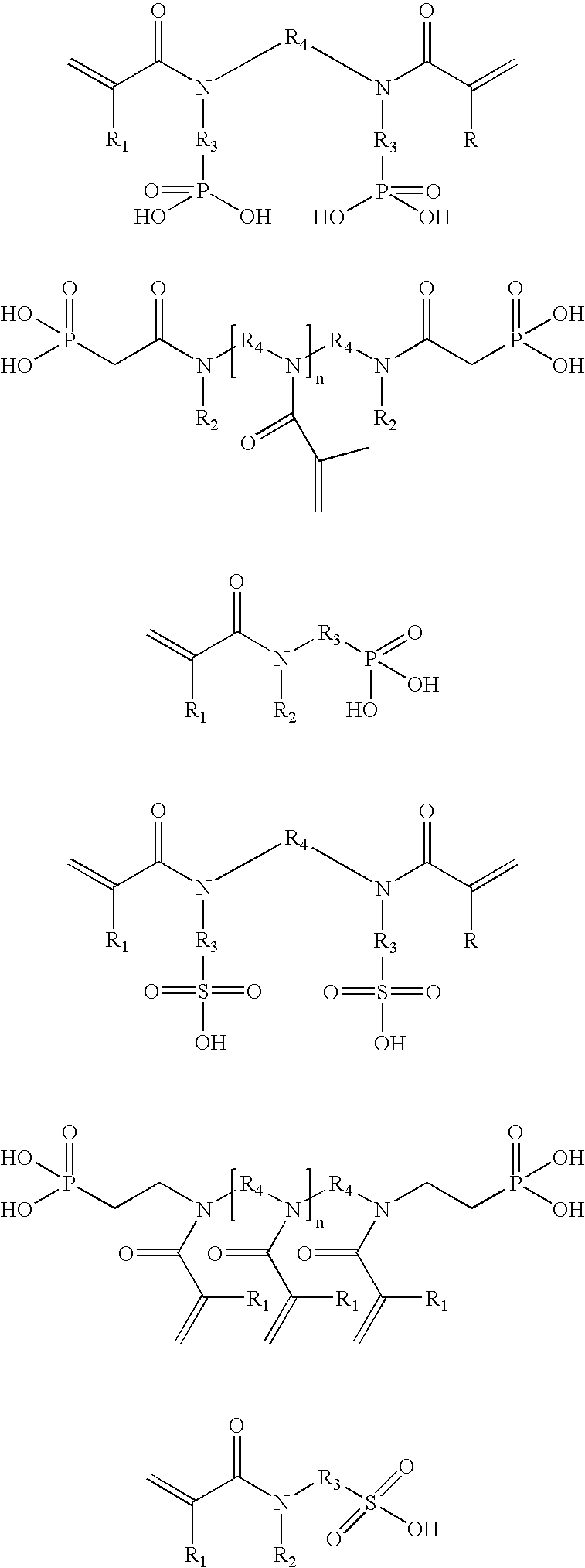
[0131] N-(3-sulfopropyl) methacrylamide (1) and N,N-bis(3-sulfopropyl) methacrylamide 21
[0132] To a stirred solution of 12 g (140.9 mmol) methacrylamide in 400 ml methylene chloride 3.38 g (140.9 mmol) sodium hydride were carefully added stepwise at a temperature of 0.degree. C. The suspension was stirred for 3 h at room temperature before 18.943 g (155 mmol) 1,3-propanesulfone were added. After 12 d stirring at room temperature 150 ml water were dropped carefully into the reaction mixture, while the temperature was kept at 0.degree. C. The aqueous layer was then separated and five times extracted with 100 ml methylene chloride. Afterwards the water was removed at a rotary evaporator and the resulting white solid washed thoroughly with acetone. The sulfonic acid sodium salt was solved again in water and poured over an ion exchange column (Merck ion exchanger 1). The resulting acidic aqueous solution was stabilized with 0.025 mol % hydroquinone and narrowed down at a rotary evaporato...
example 2
[0135] N-(6-hydroxyhexyl) methacrylamide (2)
[0136] A solution of 22.56 g (0.215 mol) methacryloyl chloride in 20 ml chloroform was dropped slowly into a stirred solution of 24.84 g (0.215 mol) N-hydroxysuccinimide in 50 ml triethylamine and 500 ml chloroform at a temperature of 0.degree. C. After the solution was stirred for 3 h at room temperature 21.07 g (0.179 mol) 6-amino-1-hexanol in 20 ml chloroform were added. The reaction mixture was stirred overnight at room temperature before the solvent was removed at reduced pressure. The residue was taken up into methylene chloride and the remaining solid was filtered off. Then the solution was narrowed down and the precipitate filtered off again. Afterwards the solution was washed twice with 200 ml of an aqueous sodium hydroxide solution (20%). The combined aqueous layers were washed four times with 100 ml methylene chloride and the combined organic solutions were then dried over magnesium sulfate. Filtration and evaporation of the sol...
example 3
[0150] N-[2-(diethoxyphosphoryl)-ethyl] acrylamide (5)
[0151] To a solution of 8.09 g (44.7 mmol) (2-aminoethyl)phosphonic acid diethyl ester in 150 ml methylene chloride a solution of 6.06 g (67 mmol) acryloyl chloride in 30 ml methylene chloride and a solution of 2.68 g (67 mmol) sodium hydroxide in 30 ml water were added simultaneously under stirring, so that the temperature remains at 0-5.degree. C. Thereafter the mixture was stirred at room temperature for additional two hours. The reaction was terminated by the addition of 100 ml water. To achieve separation of the layers some sodium chloride was added. The organic phase was separated and the aqueous solution was extracted twice with 50 ml methylene chloride. The combined organic liquids were washed with 50 ml of 1 n HCl, 50 ml of 1 n NaHCO.sub.3 and with 50 ml water. Drying over magnesium sulfate, filtration and evaporation of the solvent yielded a yellow oil as raw product. As final purification the material was chromatograph...
PUM
| Property | Measurement | Unit |
|---|---|---|
| Fraction | aaaaa | aaaaa |
| Fraction | aaaaa | aaaaa |
| Time | aaaaa | aaaaa |
Abstract
Description
Claims
Application Information