Direct, real-time imaging guidance of cardiac catheterization

a direct, real-time imaging and catheterization technology, applied in the field of cardiac catheterization and real-time, forward imaging through blood, can solve the problems of not being able to guide procedures such as angioplasty or ablation, not being able to examine the surface of the heart and vasculature, and not having access

Inactive Publication Date: 2005-01-20
OLYMPUS CORP
View PDF22 Cites 267 Cited by
  • Summary
  • Abstract
  • Description
  • Claims
  • Application Information

AI Technical Summary

Benefits of technology

[0053] In catheter ablation, the present invention provides a method and means for near-infrared-guided catheter ablation of linear lesions. The near-infrared imager consists of a fiber-optic bundle about one millimeter in diameter, which can transmit near-infrared light. This bundle is connected on the distal end to a lens assembly, which spreads the light over a 30-90 degree cone. The proximal end is inserted into an interface cable, which contains and routes the near-infrared light source and the near-infrared camera. This viewing syst

Problems solved by technology

In the United States, heart disease results in the death of almost one million people per year.
While fluoroscopy provides the cardiologist a crude guide, it does not allow examination of surfaces of the heart and vasculature or provide enough vision to guide procedures such as angioplasty or ablation.
These procedures are done in either a clear fluid or in air and cannot be performed in the presence of blood.
It is unfortunate cardiology has not had access to this technology since the common procedures would benefit from visualization.
Current methods of visualizing structures in the cardiovascular system are limited to fluoroscopy, ultrasound and angioscopy.
It has been shown that radiography, however, usually underestimates the degree of stenosis and therefore is only useful in providing a gross measure of flow.
It is of little use in guiding procedures since it does not provide a direct forward-viewing image of the target.
Patients with AF are much more prone to stroke, congestive heart failure, myocardial infarctions and fatal ventricular arrhythmias.
Patients can be in temporary (paroxysmal) atrial fibrillation or permanent atrial fibrillation (most dangerous).
This arrhythmia is usually disabling and resistant to antiarrhythmic drugs and it carries a potential risk of thromboembolism and chycardiomyopathy.
The infarct sometimes results in short-circuiting of the ventricular electrical activation pattern, resulting in tachycardia.
Since these procedures are performed without local visualization, the location of the burns cannot be seen, making connection of the spots very difficult.
Although the feasibility of anatomy-based catheter ablations been demonstrated with standard catheter ablation techniques, these procedures are extremely time-consuming, require prolonged fluoroscopy exposure and have been associated with a high incidence of complications.
A dangerous complication of this procedure is stenosis of the pulmonary veins from ablations too far inside the pulmonary veins.
Pulmonary vein stenosis can be disastrous and can lead to heart-lung transplantation.
However, the creation of a continuous and transmural lesion along the 1-6 cm if the isthmus is sometimes difficult to achieve with current RF technology designed to punctate lesions.” Oftentimes, gaps in the ablation line can produce atrial fibrillation, a more dangerous arrhythmia.
Currently, ablation of PMIT is still an experimental procedure due to an inability to visualize the infarct location.
There have been experimental attempts to accomplish disruption of the short circuit using focal burns; however, this has been restricted to a minority type of PMIT (monomorphic PMIT accounting for <10% of PMIT patients).
In general, these linear-lesion producing catheters have two problems: variations in cardiac anatomy and inability to assess lesion production.
If a circular configured catheter, such as Stewart (U.S. Pat. No. 6,325,797), were used in pulmonary veins which are contiguous to each other, some of the

Method used


Image

  • Direct, real-time imaging guidance of cardiac catheterization
  • Direct, real-time imaging guidance of cardiac catheterization
  • Direct, real-time imaging guidance of cardiac catheterization

Examples


Embodiment Construction

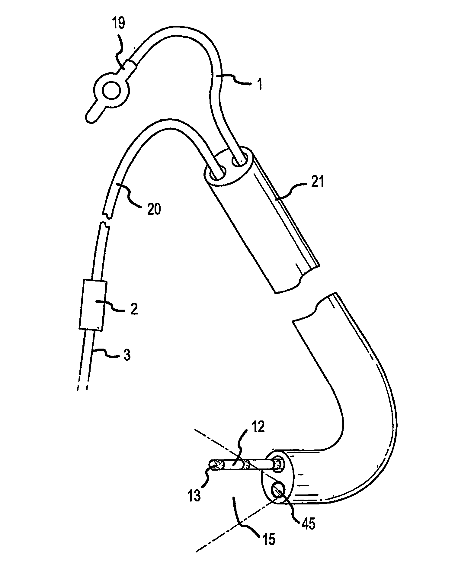
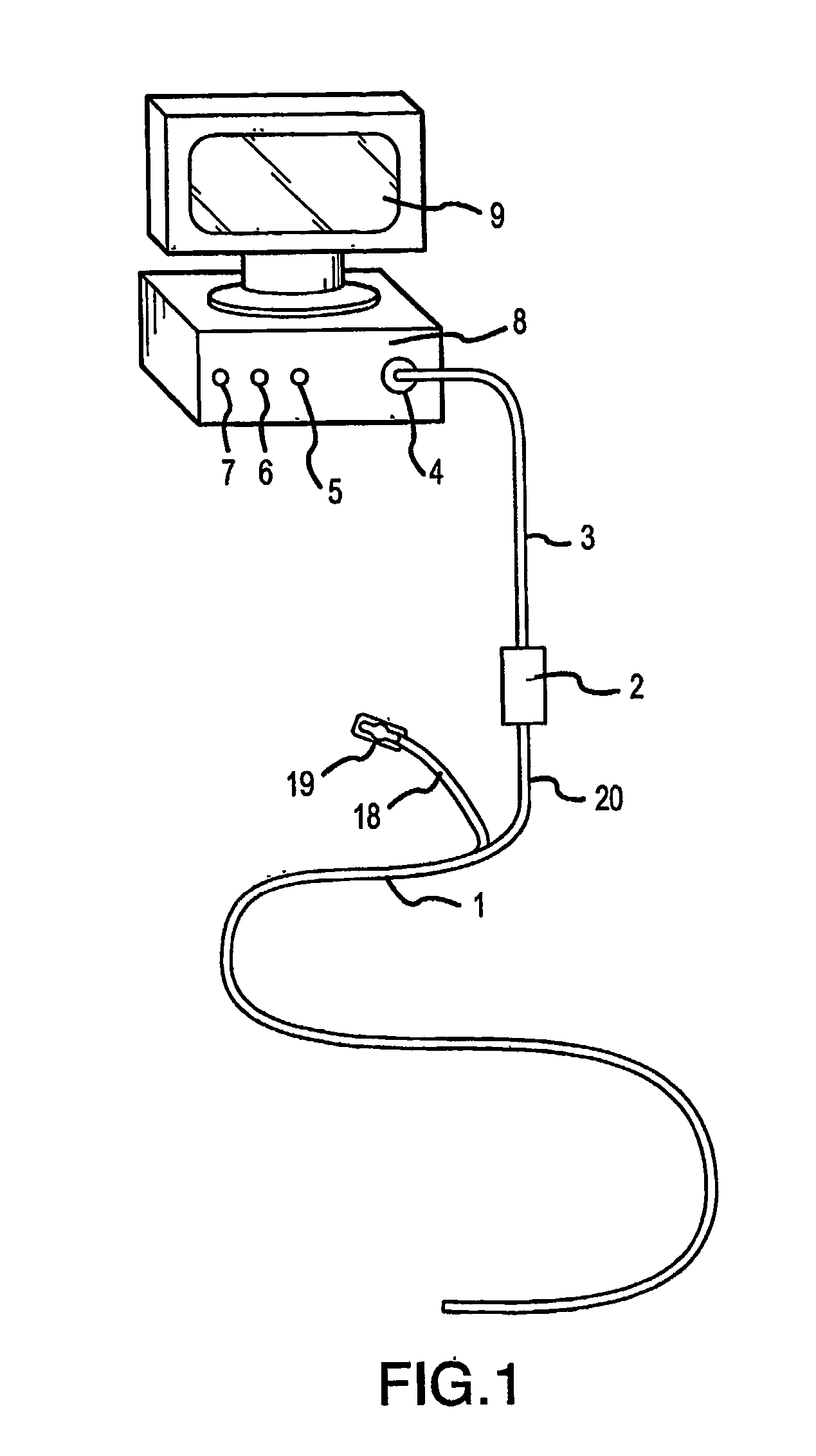
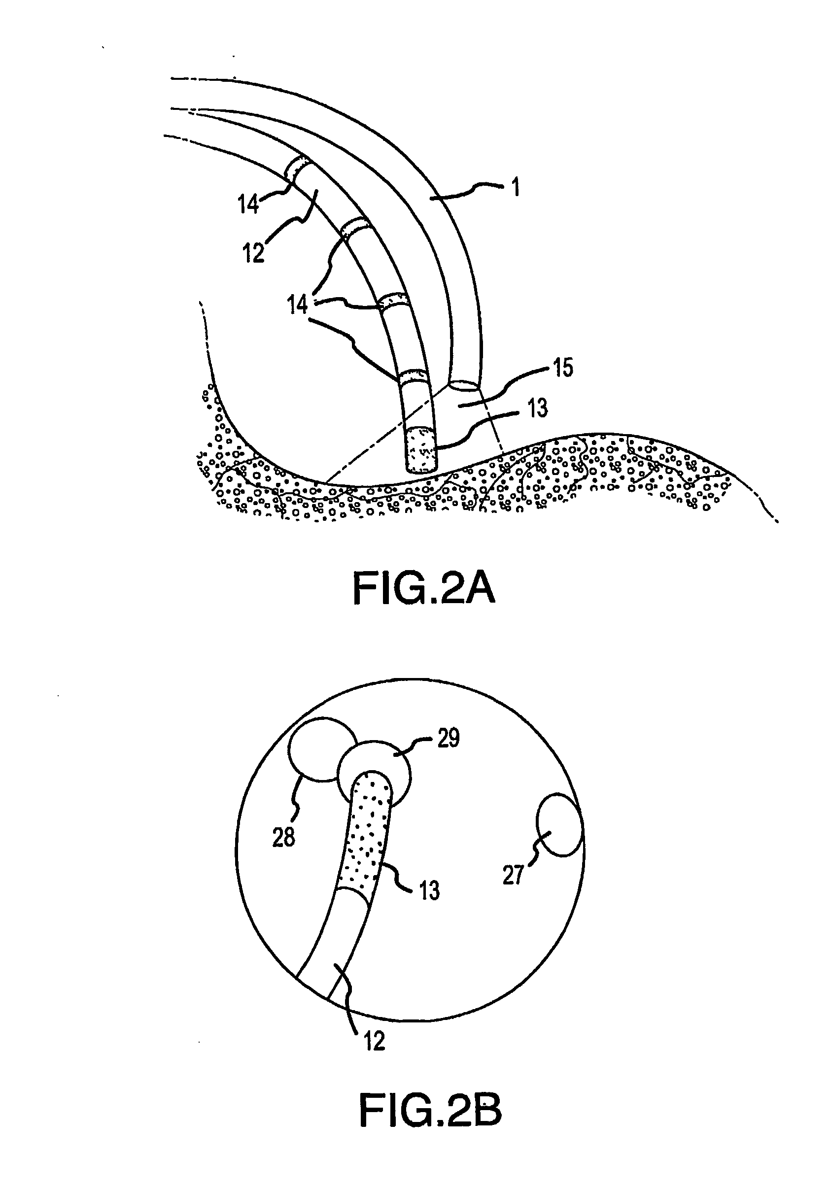
[0082]FIG. 1 shows the near-infrared imaging endoscope system. The system consists of a near-infrared endoscope (1). The endoscope (1) bifurcates into two segments, one branch (18) containing the wires for the articulation mechanism goes to a handle (19) with a control to articulate the catheter distal end. The bifurcation (20) contains the optical fibers, which are connected to an interface box (2) containing the light source and imaging sensor. The fiber assembly consists of illumination and imaging fibers with lenses placed on both ends of the catheter. A cable (3) to the near-infrared imaging acquisition unit (8) [we don't use that term in old patent] as described in U.S. Pat. No. 6,178,346, connects to the interface box (2). The acquisition unit (8) contains the system controller and image processing software and imaging controls (5, 6, 7). The acquisition unit (8). The details of the infrared-imaging are described in U.S. Pat. No. 6,178,346 and thus need not be repeated in det...


PUM


Abstract

Devices (1) and methods for accomplishing tasks within a body using infrared imaging are disclosed which, in connection with other known components, are useful in ablation, stitching and other operations, identification of sizes and composition of objects, and the creation of maps by taking multiple images at different positions or times.

Description

[0001] This application claims the benefit of U.S. provisional patent application No. 60 / 332,654 filed on Nov. 9, 2002.BACKGROUND OF THE INVENTION [0002] 1. Field of the Invention [0003] This invention relates to cardiac catheterization and real-time, forward imaging through blood. [0004] 2. Related Art [0005] The following references provide useful information in the filed of the present invention, and are incorporated by reference herein: PeronneauNovember 19703,542,014CarpentierApril 19723,656,185MoulopoulosJune 19723,671,979BoretosNovember 19774,056.854CribierOctober 19884,777,951CraggMay 19905,085,635FischellJune 19935,219,329DraslerMay 19955,370,609LaurJune 19955,399,158AvitallJanuary 19965,487,385EdwardsSeptember 19965,546,662LodderSeptember 19965,553,610KotulaOctober 19965,569,275SwansonDecember 19965,582,609SwartzDecember 19985,846,223ShearonJuly 19996,064,902HaissauguerreMay 20006,064,902AmundsonJanuary 20016,178,346SuorsaMarch 20016,206,831YoshidaMay 20016,226,076TuMay 2...

Claims


Application Information

Patent Timeline
IPC IPC(8): A61BA61B19/00A61B1/00A61B1/018A61B1/04A61B1/06A61B5/05A61B18/12A61B18/14A61B18/18A61MA61M25/00A61M25/01
CPCA61B1/018A61B8/12A61B18/1492A61M25/0105A61B2018/00351A61B2019/5231A61B19/52A61B90/36A61B2090/373A61B5/4848
Inventor AMUNDSON, DAVIDHANLIN, H. JOHNBLANKENSHIP, LARRY
Owner OLYMPUS CORP
Why Eureka
Try Eureka