
Image formation on heat-developable light-sensitive material and image forming apparatus

a technology of light-sensitive materials and image formation, which is applied in the direction of photosensitive materials, instruments, printers, etc., can solve the problems of failure to design a sufficiently sensitive system, desensitization of spectrally sensitive heat-developable light-sensitive materials during storage, etc., and achieves high sensitivity, high quality, and high density

Inactive Publication Date: 2005-02-03
FUJIFILM CORP
View PDF7 Cites 1 Cited by
  • Summary
  • Abstract
  • Description
  • Claims
  • Application Information

AI Technical Summary

Benefits of technology

The light-sensitive material can have arbitrary gradient. For effective manifestation of the effects of the invention, a preferred average contrast between 1.5 density and 3.0 density is 1.5 to 10. The terminology “average contrast” as used herein means the slope of the straight line connecting optical density 1.5 and optical density 3.0 in a characteristic curve with a logarithm of a laser exposure plotted as abscissa and an optical density as ordinate. The above-recited average contrast of 1.5 to 10 is preferred for preventing cuts of letters. A still preferred average contrast is 2.0 to 7, particularly 2.5 to 6.
, a preferred average contrast between 1.5 density and 3.0 density is 1.5 to 10. The terminology “average contrast” as used herein means the slope of the straight line connecting optical density 1.5 and optical density 3.0 in a characteristic curve with a logarithm of a laser exposure plotted as abscissa and an optical density as ordinate. The above-recited average contrast of 1.5 to 10 is preferred for preventing cuts of letters. A still preferred average contrast is 2.0 to 7, particularly 2.5 to 6.
The light-insensitive organic silver salt which can be used in the invention is a silver salt which is relatively stable to light but capable of forming a silver image when heated to 80° C. or higher in the presence of an irradiated photocatalyst (e.g., a latent image of a light-sensitive silver halide) and a reducing agent. Any organic substance containing a source capable of reducing silver ions can be used as a reducing agent.
Such light-insensitive organic silver salts are described, e.g., in JP-A-10-62899 (para. Nos. 0048-0049), EP 0803764A1 (page 18, line 24 to page 19, line 37), EP 0962812A1, JP-A-11-349591, JP-A-12-7683, and JP-A-12-72711. Silver salts of organic acids, particularly long-chain fatty acids having 10 to 30, preferably 15 to 28, carbon atoms, are preferred. Suitable fatty acid silver salts include silver behenate, silver arachidate, silver stearate, silver oleate, silver laurate, silver caproate, silver myristate, silver palmitate, and mixtures thereof. Preferred of them are silver behenate and a mixed fatty acid silver salt having a silver behenate content of 50 mol % or more, particularly 80 mol % or more, especially 96 mol % or more.
The shape of the organic silver salt includes, but is not limited to, a needle shape (acicular), a rod shape, a tabular shape, and a flaky shape. A flaky organic silver salt is preferred in the invention. Rod-like (aspect ratio: 5 or smaller), parallelopipedal, cubic or potato-like amorphous grains are also preferred. Organic silver salts having these preferred shapes are favorably characterized by undergoing less fogging in heat development than needle-like grains having an aspect ratio greater than 5.
In this invention “flaky organic silver salt” is defined as follows. An organic silver salt is observed under an electron microscope. The shapes of the individual organic silver salt grains are approximated to parallelepipeds with the shortest side a, the middle side b, and the longest side c (the sides b and c can be equal). A ratio x of the next shortest side length to the shortest side length is obtained (x=b / a). Values x -are calculated for about 200 grains to obtain an average x. Grains having an average x equal to or greater than 1.5 are defined to be “flaky”. A preferred average x is 1.5 to 30, particularly 2.0 to 20. Incidentally, an average x of needle-like acicular particles is smaller than 1.5 and not smaller than 1.

Problems solved by technology

However, spectrally sensitized heat-developable light-sensitive materials undergo desensitization during storage due to gradual decomposition of the spectral sensitizers with time.
Nevertheless, the method disclosed failed to design a sufficiently sensitive system and was insufficient for assuring necessary image quality, i.e., sharpness.

Method used


Image

  • Image formation on heat-developable light-sensitive material and image forming apparatus
  • Image formation on heat-developable light-sensitive material and image forming apparatus
  • Image formation on heat-developable light-sensitive material and image forming apparatus

Examples


example 1

1) Preparation of PETP Support

Polyethylene terephthalate (PETP) having an intrinsic viscosity IV of 0.66 (measured in phenol / tetrachloroethane=6 / 4 at 25° C.) was prepared from terephthalic acid and ethylene glycol in a conventional manner. PETP was pelletized, dried at 130° C. for 4 hours, melted at 300° C., and mixed with 0.04% of dye BB shown below. The molten mixture was extruded through a T-die and quenched to obtain an unstretched film which would have a thickness of 175 μm after biaxial stretch and heat set.

The film was stretched 3.3 times in the machine direction by means of rolls having different peripheral speeds and then 4.5 times in the transverse direction with a tenter at 110° C. and 130° C., respectively. The biaxially stretched film was heat set at 240° C. for 20 seconds, followed by relaxation at the same temperature in the transverse direction. Both lateral edges were trimmed and knurled, and the film was wound under tension of 4 kg / cm2 into a roll.

2) Corona...

example 2

Silver halide emulsions-2, -3, and -6 having the uniform halogen composition shown in Table 1 were prepared in the same manner as for emulsion-1 of Example 1 except for changing the halogen composition. Light-sensitive materials were prepared by using these emulsions in the same manner as in Example 1 (designated samples 2, 3, and 6). The temperature condition in silver halide grain formation was controlled so that the resulting silver halide emulsion grains might have an average sphere-equivalent diameter of 40 nm.

example 3

1) Preparation of Silver Halide Emulsion-4 and Sample 4 To 1421 ml of distilled water was added 3.1 ml of a 1% potassium bromide solution, and 3.5 ml of 0.5 mol / l sulfuric acid and 31.7 g of phthalated gelatin were added to the solution. While stirring the mixture in a stainless steel reaction vessel at a liquid temperature of 32° C., solution A prepared by diluting 22.22 g of silver nitrate with distilled water to make 95.4 ml and solution B prepared by diluting 15.6 g of potassium bromide with distilled water to make 97.4 ml were added to the mixture at a constant rate over 45 seconds.

To the mixture were added 10 ml of a 3.5% hydrogen peroxide aqueous solution and then 10.8 ml of a 10% benzimidazole aqueous solution. Solution C prepared by diluting 30.64 g of silver nitrate with distilled water to make 187.6 ml was added to the mixture at a constant rate over 12 minutes. Simultaneously with this addition, solution D prepared by diluting 21.5 g of potassium bromide with distille...


PUM


Abstract

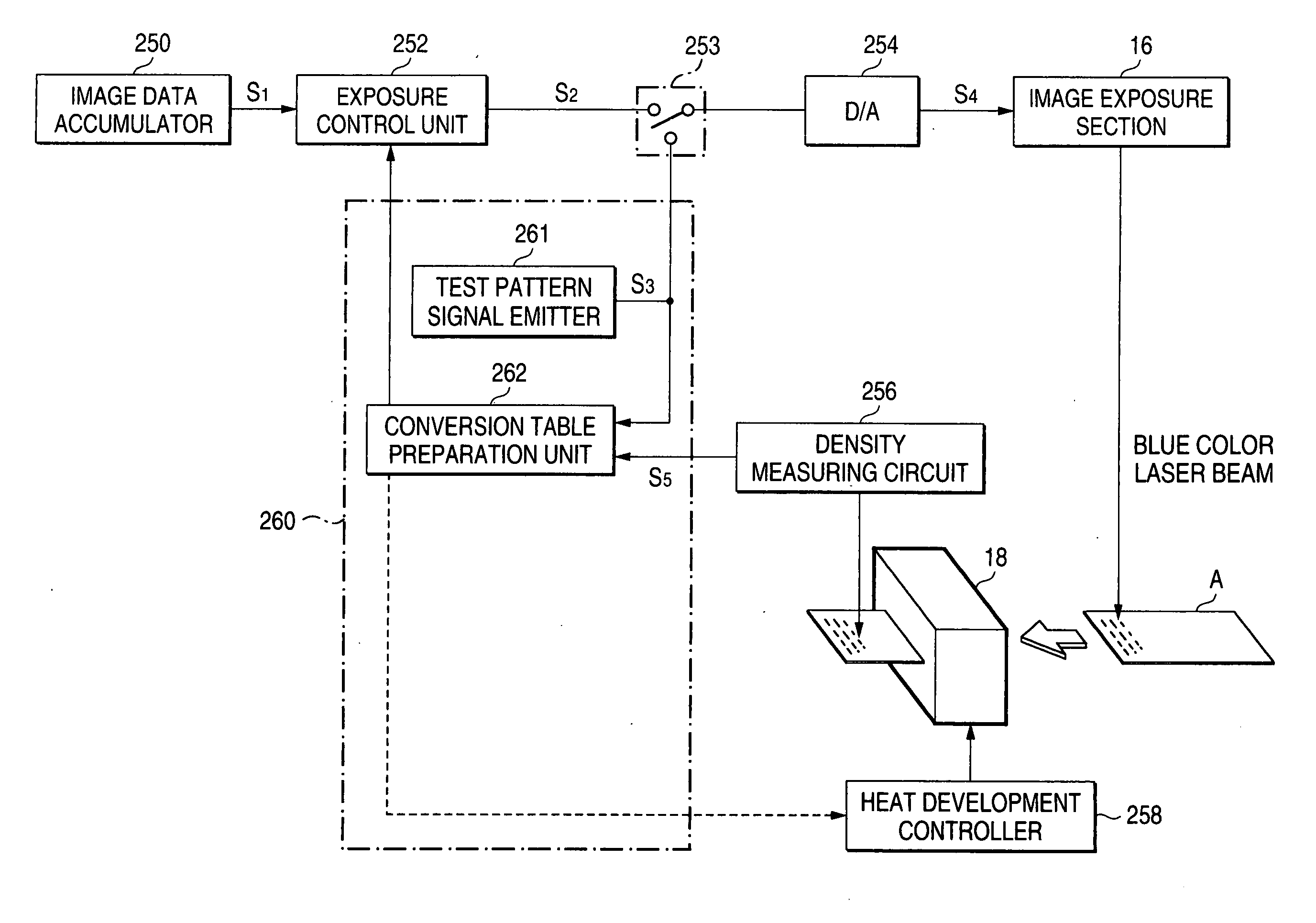
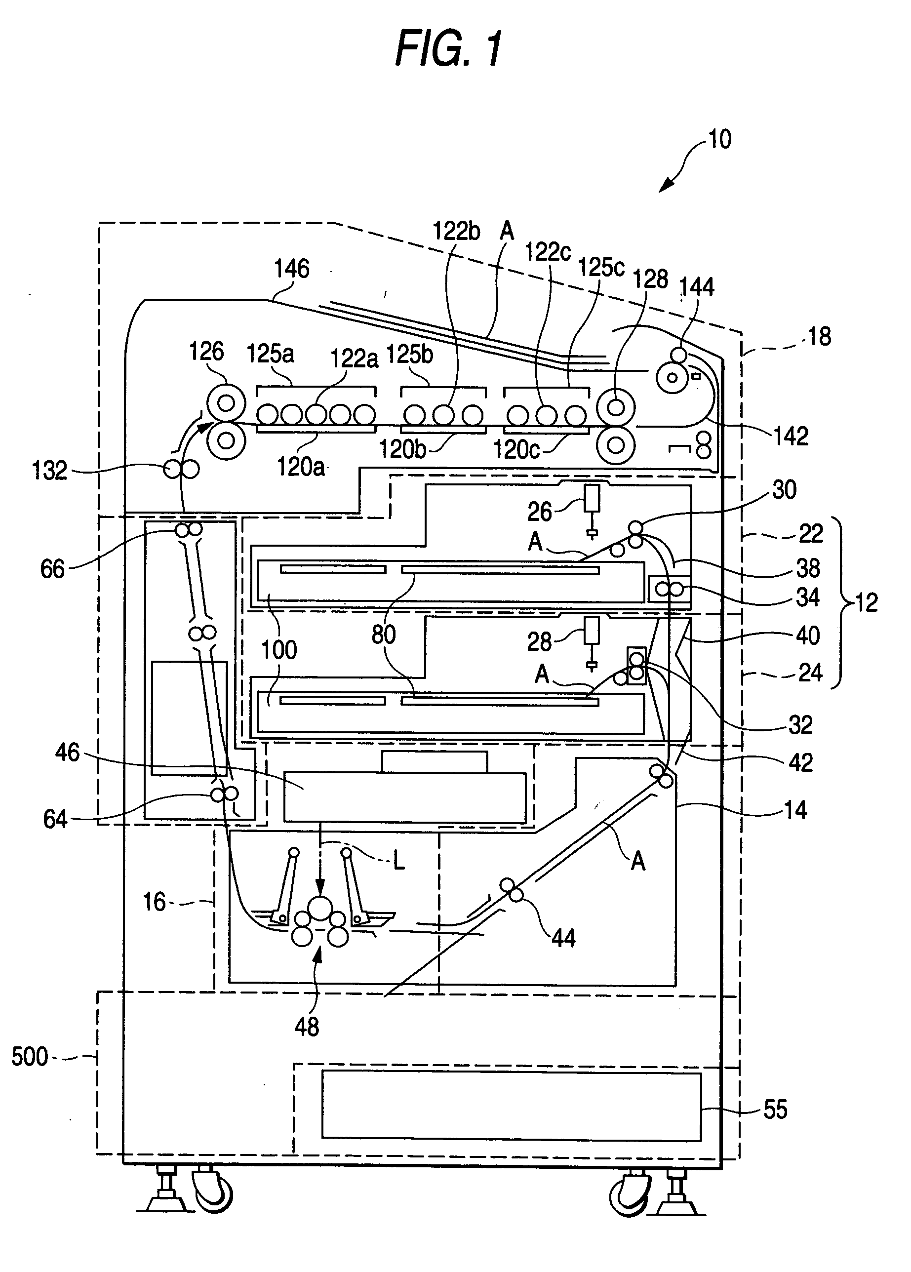
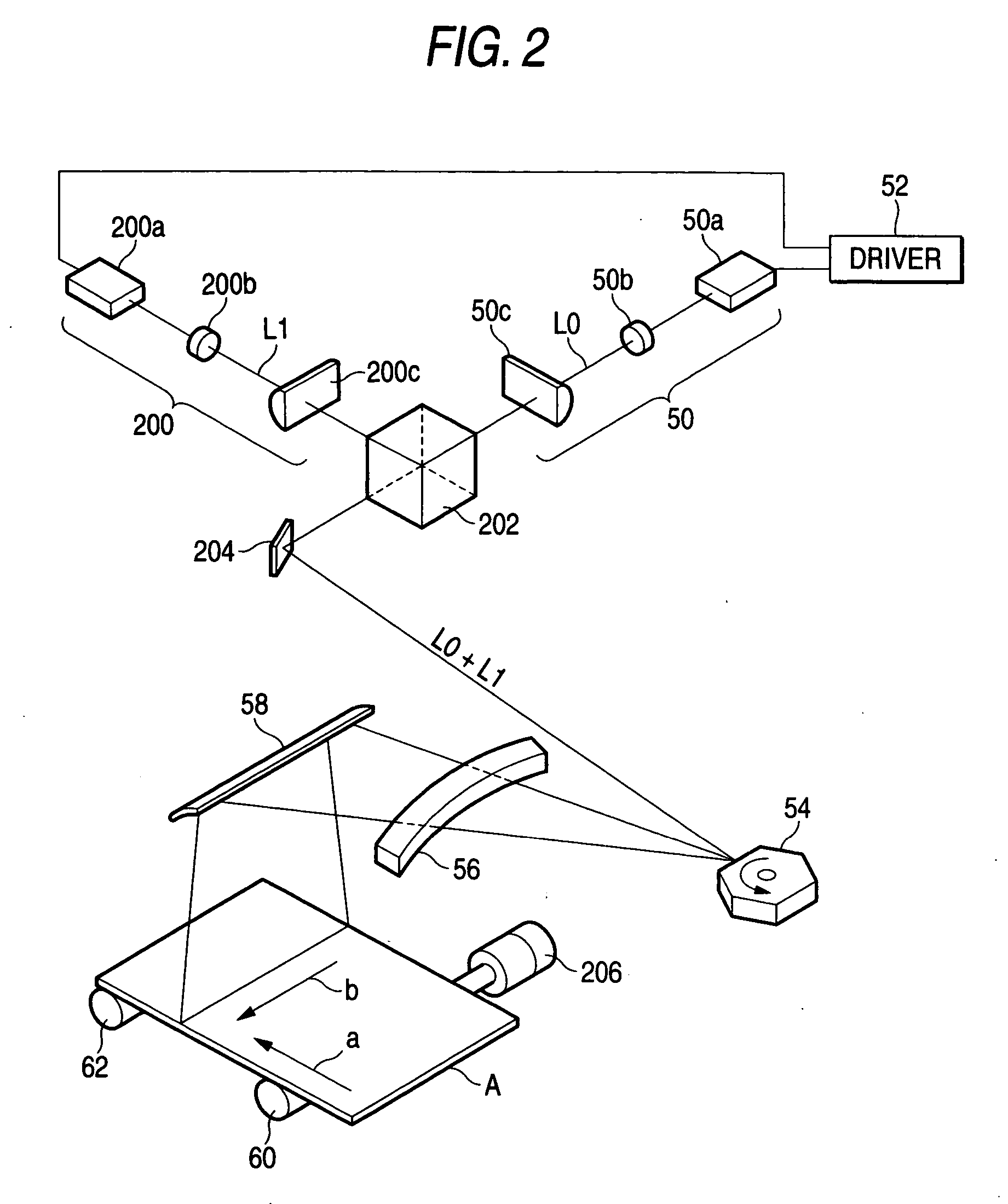
An image forming method comprising exposing a heat-developable light-sensitive material comprising a support having thereon at least a light-sensitive silver halide having a silver iodide content of 5 to 100 mol %, a light-insensitive organic silver salt, a heat developing agent, and a binder by means of a scanning optical system having a light source emitting a laser beam having an emission peak between 350 nm and 450 nm to form a latent image on said heat-developable light-sensitive material, heating said heat-developable light-sensitive material to about 80 to 250° C. in a heat development section, and cooling said heat-developable light-sensitive material having been heat treated in said heat development section to or below a development stopping temperature while said heat-developable light-sensitive material is transported in a cooling section.

Description

BACKGROUND OF THE INVENTION 1. Field of the Invention This invention relates to a technique for high-sensitivity high-precision imaging and size reduction of an imaging apparatus used for a dry image recording system. 2.Description of the Related Art Imaging apparatus for obtaining diagnostic hard copy images by digital radiography using storage phosphor imaging plates, CT imaging, MR imaging, etc. have adopted a wet system wherein a silver salt photographic material is exposed and wet-processed. On the other hand, a dry system recording apparatus involving no wet chemical processing has recently engaged attention. Light-sensitive and / or heat-sensitive heat-developable photographic materials or heat-developable photographic films (hereinafter inclusively referred to as heat-developable light-sensitive materials) are used in a dry system recording apparatus. In a dry system recording apparatus, a heat-developable light-sensitive material is irradiated (scanned) with a laser beam...

Claims


Application Information

Patent Timeline
IPC IPC(8): G03C1/498G03B27/32G03C5/08G03D13/00
CPCG03D13/002G03C1/49881
Inventor GOTO, YASUHIKOYAMANE, KATSUTOSHI
Owner FUJIFILM CORP
Learn More