Method and apparatus for cooling in hydrogen plants

a hydrogen plant and reformate gas technology, applied in the direction of lighting and heating apparatus, electrochemical generators, hydrogen separation using solid contact, etc., can solve the problems of water vapor condensation, water vapor adsorption, and the psa system's adsorbents are extremely sensitive to water vapor, so as to improve the efficiency and operability of hydrogen plants, without the penalty of high energy consumption and operational complexity

Inactive Publication Date: 2005-12-01
H2GEN INNOVATIONS INC
View PDF7 Cites 31 Cited by
  • Summary
  • Abstract
  • Description
  • Claims
  • Application Information

AI Technical Summary

Benefits of technology

[0012] In an effort to improve the efficiency and operability of hydrogen plants, the inventors have formulated various improvements as described below. For example, the present invention provides an improved hydrogen...

Problems solved by technology

This cooling causes the saturation pressure of water to decrease, and thus leads to the condensation of liquid water.
The adsorbents utilized in PSA systems are extremely sensitive to water vapor.
Low temperatures greatly improve selectivity and capacity of the adsorbents, although extremely low temperatures may adversely effect the kinetic parameters of the adsorbents.
If the reformate temperature drops below the freezing point of water, then the piping of the hydrogen plant may become blocked by ice.
Such blockages could cause a safety hazard, and certainly would lead to a need to shut the hydrogen plant down for sufficient time to remove the ice blockage.
Such systems suffer from high capital and operational costs.
Mechanical refrigeration cycles require substantial amounts of energy to operate, and cooling towers or other evaporative cooling systems require ca...

Method used


Image

  • Method and apparatus for cooling in hydrogen plants
  • Method and apparatus for cooling in hydrogen plants
  • Method and apparatus for cooling in hydrogen plants

Examples


second embodiment

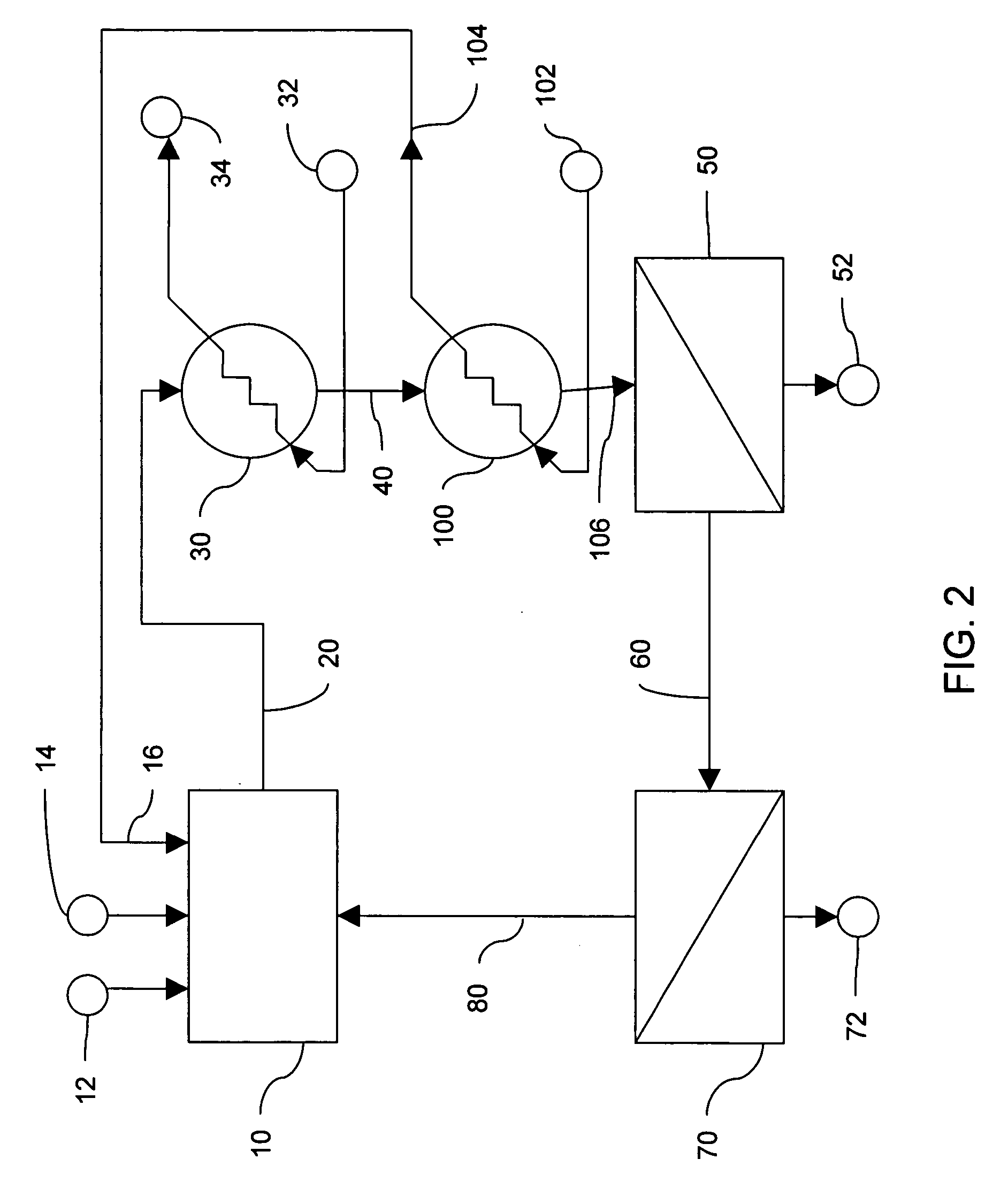
[0043] the invention is shown in FIG. 2. The hydrogen plant depicted in FIG. 2 utilizes the same general system layout as the previous embodiment of FIG. 1. However, in the second preferred embodiment of FIG. 2, cool purified water is used as the cooling fluid which is input into the supplemental cooling system 100 at inlet 102. The output of cooling fluid in outlet conduit 104 is then input to the fuel reforming plant 10 at the purified water inlet 16. This second preferred embodiment takes advantage of the fact that purified water is supplied from a water supply that utilizes a cool subterranean environment as a heat sink either at its source or during transportation of the water, such as a municipal water supply, industrial water supply, well water supply, fresh water sources, or the like, and thus is generally cooler in temperature than ambient air during periods of hot weather. Utilizing this purified water for supplemental cooling of wet reformate enhances the PSA recovery of ...

third embodiment

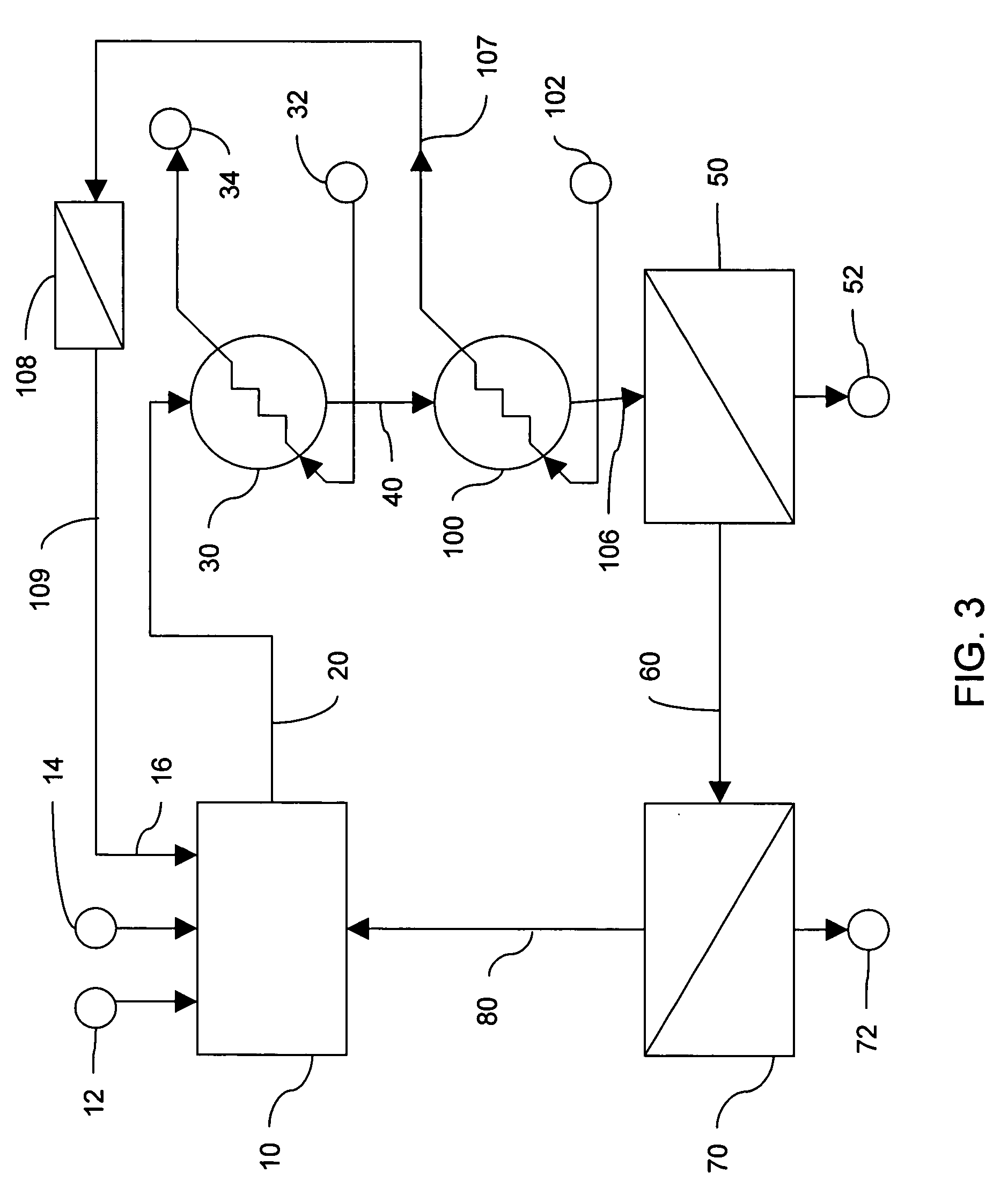
[0044] the invention is shown in FIG. 3. The hydrogen plant depicted in FIG. 3 utilizes the same general system layout as the previous embodiments of FIGS. 1 and 2. However, in the third preferred embodiment of FIG. 3, cool raw water is used as the cooling fluid which is input into the supplemental cooling system 100 at inlet 102. The output of cooling fluid in outlet conduit 107 is then passed through a separate purifier 108, such as a reverse osmosis purifier, before being input into the purified water input 16 of the fuel reforming plant 10 via conduit 109. This embodiment takes advantage of the fact that raw water from a water supply that utilizes a cool subterranean environment as a heat sink, such as a municipal water supply, industrial water supply, well water supply, fresh water supply, or the like, is generally cooler in temperature than ambient air during periods of hot weather. Utilizing this water for supplemental cooling of wet reformate enhances the PSA recovery of the...

fourth embodiment

[0046] The heat exchanger of the present invention may be advantageously used to cool reformate in any hydrogen plant where local soil temperature is lower that the ambient air temperature. In the second and third exemplary embodiments, the use of the supply water, or process feedwater, can cause an undesirable reduction in thermal efficiency of the fuel reforming plant 10. This is because the purified process feedwater traveling through conduits 104, 107, or 122 is heated above its lowest possible temperature. If it is used as a heat exchange media for cooling a process stream, the efficiency of that heat exchange will be reduced. If, however, the impure waste water is used in the fourth embodiment, then the efficiency reduction does not occur.

[0047] An exemplary case is in the steam reforming process of U.S. Pat. Nos. 6,623,719 and 6,497,856 and U.S. application Ser. No. 10 / 791,746 In these processes, hot combustion product, or fluegas, is cooled by generating steam. The fluegas i...


PUM


Abstract

A hydrogen plant including a fuel reforming plant configured to receive and process hydrocarbon feedstock and configured to discharge wet reformate including a hydrogen-containing gas stream, and a condenser configured to cool the wet reformate. The hydrogen plant also includes a water separator configured to receive the cooled wet reformate, remove water from the wet reformate, and discharge dry reformate. The hydrogen plant further includes a hydrogen purifier configured to receive the dry reformate, process the dry reformate, and discharge pure or substantially pure hydrogen. A supplemental cooling system is provided in the hydrogen plant to cool the wet reformate in addition to the condenser.

Description

BACKGROUND OF THE INVENTION [0001] 1. Field of the Invention [0002] The present invention relates to method and apparatus for cooling reformate gas in a hydrogen plant. [0003] 2. Discussion of the Background [0004] Hydrogen has been commercially produced from hydrocarbon feedstocks since the turn of the century. Modern hydrogen plants fueled by natural gas, liquefied petroleum gas (LPG) such as propane, or other hydrocarbons are an important source of hydrogen for ammonia synthesis, petroleum refining, and other industrial purposes. These hydrogen plants share a common family of processing steps, which is referred to as “reforming,” to convert the hydrocarbon feedstock to a hydrogen-containing gas stream, which is referred to as “reformate.” Reformate gas usually contains at least twenty-fine percent water vapor by volume when it leaves the reforming process plant. [0005] Pure hydrogen or substantially pure hydrogen is manufactured from reformate gas. This hydrogen may have a purity...

Claims


Application Information

Patent Timeline
IPC IPC(8): B01J7/00B01J19/00C01B3/26C01B3/38C01B3/56F28B9/06
CPCB01J19/0013Y02E60/36C01B3/382C01B3/56C01B2203/0205C01B2203/0244C01B2203/043C01B2203/0495C01B2203/0844C01B2203/0883C01B2203/142C01B2203/146C01B2203/148C01B2203/82F28B9/06Y02E60/324B01J2219/00006C01B3/00C01B3/24C01B3/26Y02E60/32
Inventor LOMAX, FRANKLIN D. JR.NASSER, KHALIL M.
Owner H2GEN INNOVATIONS INC
Why Eureka
Try Eureka