Adherent apatite coating on titanium substrate using chemical deposition

a technology of adhesion and apatite, applied in the field of orthopedic and dental implants, can solve the problems of increasing the possibility of implant loosening, insufficient load-bearing area, implant failure, etc., and achieves faster and better coating coverage, the effect of increasing the adhesion and coverage of the coating on the substra

a technology of adhesion and apatite, applied in the field of orthopedic and dental implants, can solve the problems of increasing the possibility of implant loosening, insufficient load-bearing area, implant failure, etc., and achieves faster and better coating coverage, the effect of increasing the adhesion and coverage of the coating on the substra

US20060062925A1Inactive Publication Date: 2006-03-23NEW YORK UNIV

Image

  • Adherent apatite coating on titanium substrate using chemical deposition
  • Adherent apatite coating on titanium substrate using chemical deposition
  • Adherent apatite coating on titanium substrate using chemical deposition

Examples


Embodiment Construction

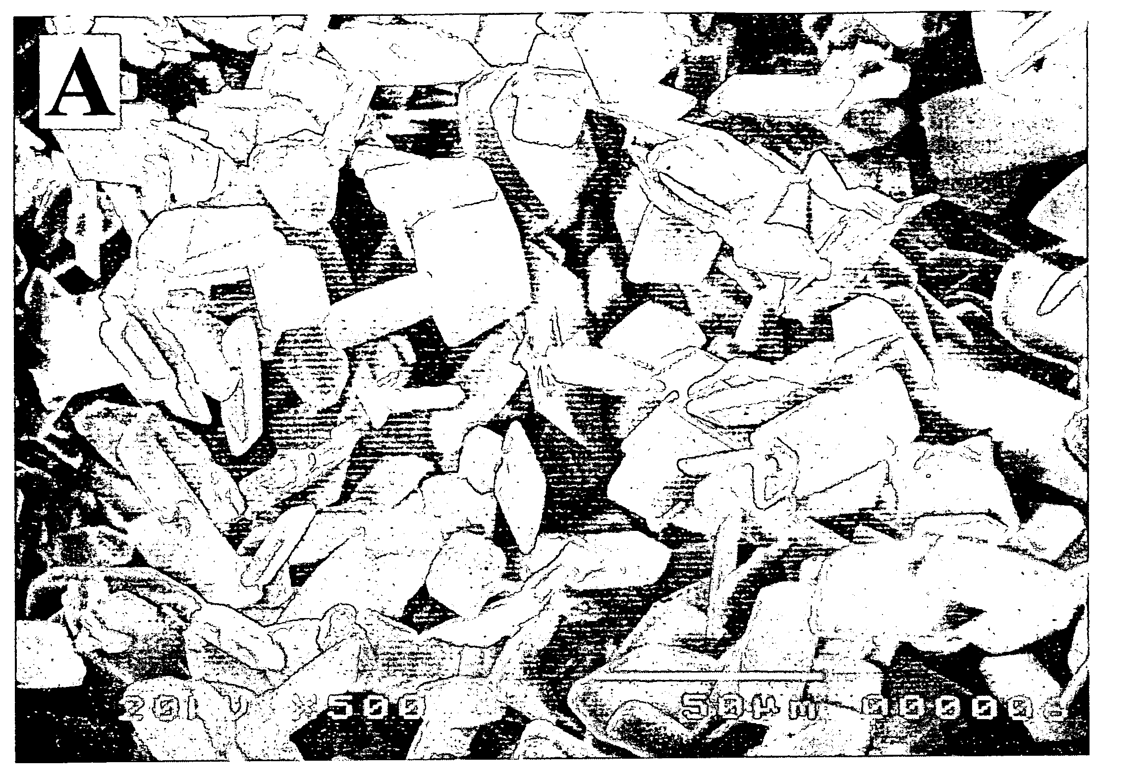
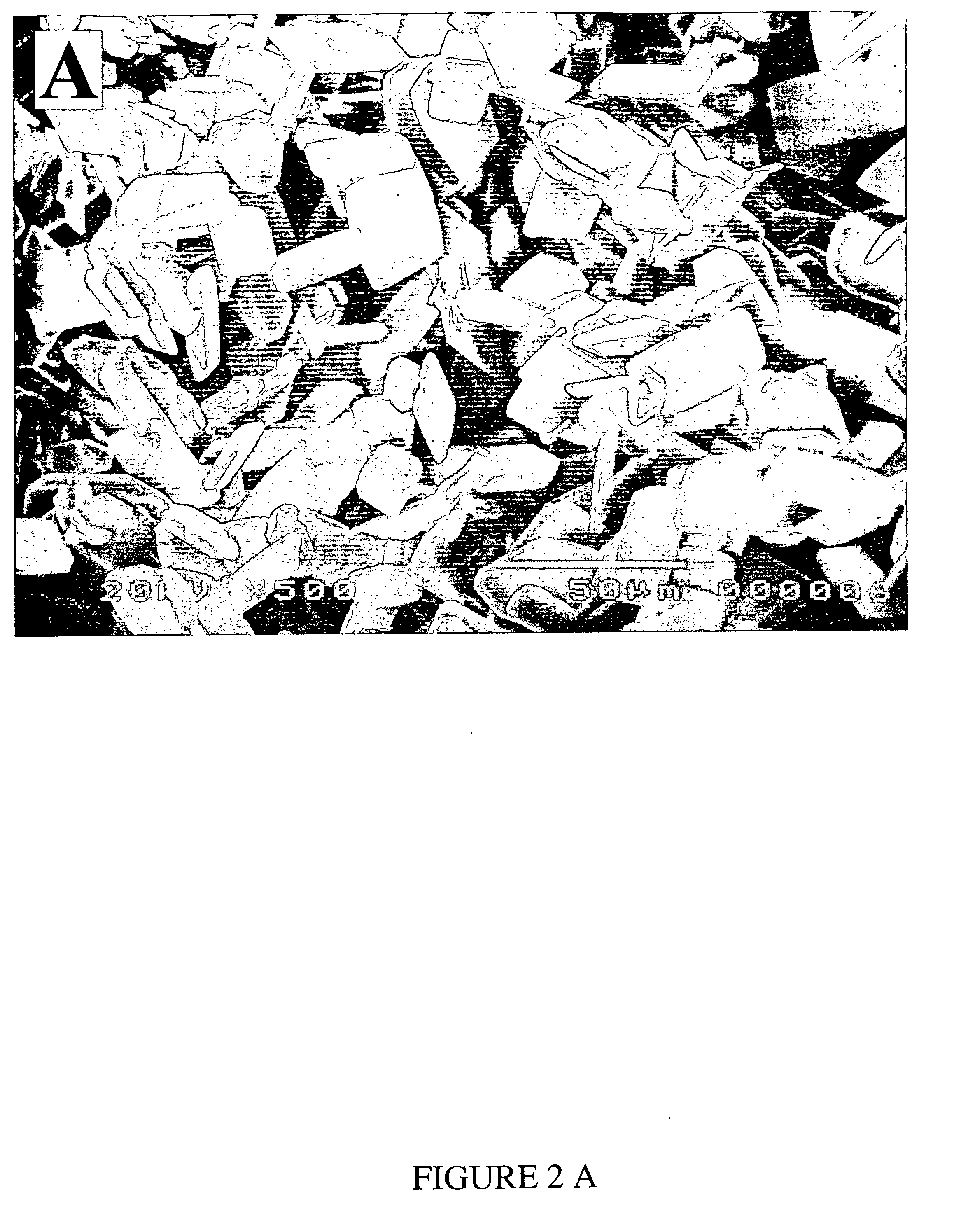
[0031] Sample Preparation: Sixty commercially pure titanium (Cp-Ti, ASTM B-265) discs (2 mm thickness and 12.7 mm diameter) were polished with 320, 400, and 600 grit papers using a grinding machine (Buehler, Phoenix Beta), ultrasonically cleaned in baths of doubly distilled (ddw), acetone, ddw, ethanol, and ddw (10 min in each bath), and then air-dried.

[0032] Two Step Apatite coating: the discs were immersed in a calcifying solution prepared by mixing 200 mM CaCO3+100 mM NaH2PO4.H2O and dissolving the mixed reagents with 2.9% H3PO4 solution. The pH of the solution was 2.67 at room temperature. The discs were placed on the bottom of a sealed container and kept in oven at 75° C. for 24 h. 10 discs were placed in each container with 100 ml of calcifying solution. The discs were then removed from the solution, rinsed three times in distilled water, and air-dried. After removing the discs, the pH of the calcifying solution was 2.81 at room temperature. In the second step, to convert the...


PUM

PropertyMeasurementUnit
Temperatureaaaaaaaaaa

Abstract

An adherent bioactive calcium phosphate coating is formed on a titanium or titanium alloy substrate by immersing the substrate in an acidic calcium phosphate solution to form a non-apatitic calcium phosphate coating on the substrate. In a second step the coated substrate can be converted to a less reactive coating by being immersed into a basic or neutral solution to convert the coating into an apatite. However if a relatively reactive coating is desired, the second step can be dispensed with.

Description

RELATED APPLICATION [0001] This application claims priority from U.S. Provisional Application Ser. No. 60 / 612,063, filed Sep. 22, 2004.FIELD OF INVENTION [0002] This invention relates generally to the manufacture of orthopedic and dental implants, and more specifically relates to a process for chemical disposition of a bioactive calcium phosphate coating on the Ti and Ti alloys which are the metals of choice for fabrication of such implants. BACKGROUND OF INVENTION [0003] Commercially pure titanium (Ti) and Ti alloys are the metals of choice in orthopedic and dental applications because of their biocompatibility, resistance to corrosion and good mechanical properties such as lightweight, durability, high strength, and the ability to be prepared in different forms, shapes and textures. However, Ti or Ti alloy do not directly bond or attach to bone. Instead, there is a layer of fibrous tissue at the Ti-bone interface causing a weak interface that could increase the possibility of the ...

Claims


Application Information

Patent Timeline
23 Mar 2006
Publication
US20060062925A1
IPC
B05D1/18
CPC
A61L27/32; A61L27/06; C23C22/22
Inventors
ROHANIZADEH, RAMIN; LEGEROS, RACQUEL Z.